Systems and Methods for Displaying Multi-Energy Data

Active Publication Date: 2010-05-27
GENERAL ELECTRIC CO
View PDF11 Cites 40 Cited by
  • Summary
  • Abstract
  • Description
  • Claims
  • Application Information

AI Technical Summary

Problems solved by technology

Due to this relationship, images acquired with a polychromatic x-ray beam suffer from beam hardening artifacts.
Known systems and methods are not equipped to provide clinical insight i

Method used


Image

  • Systems and Methods for Displaying Multi-Energy Data
  • Systems and Methods for Displaying Multi-Energy Data
  • Systems and Methods for Displaying Multi-Energy Data

Examples


Embodiment Construction

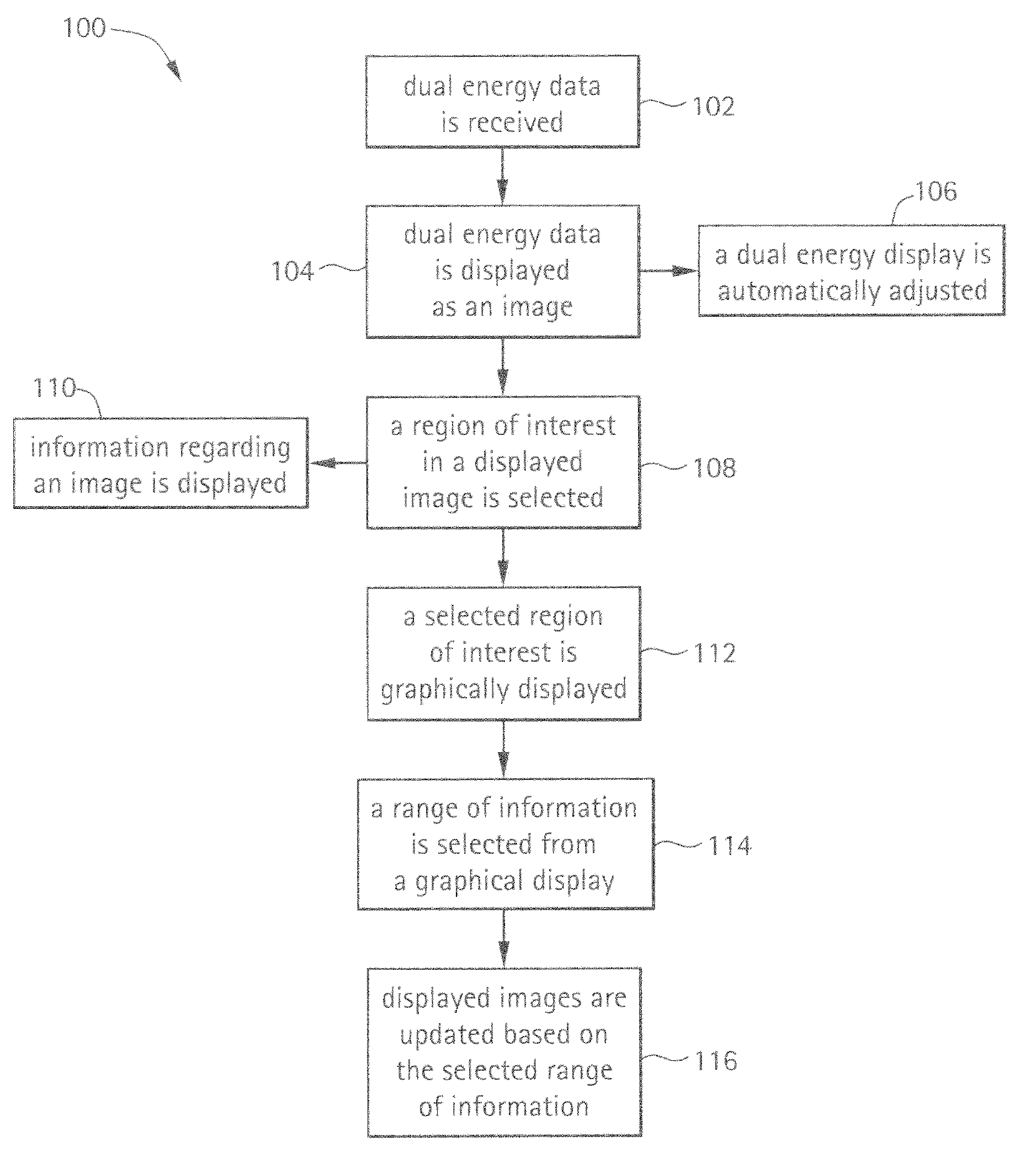
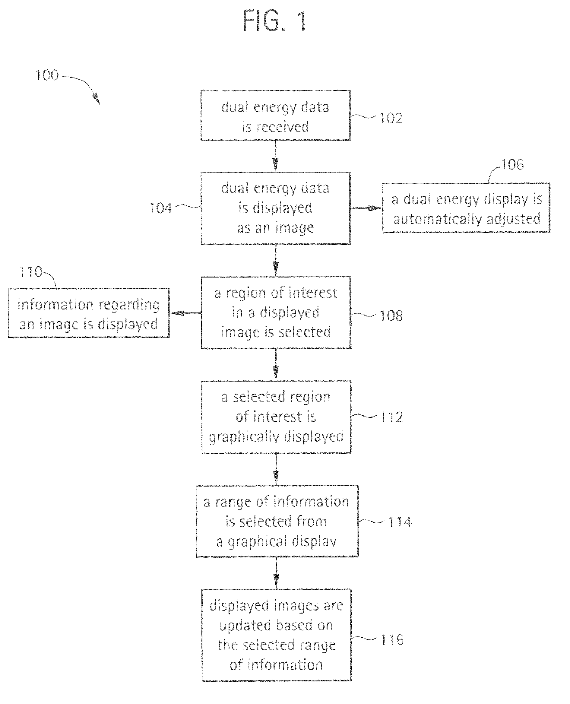
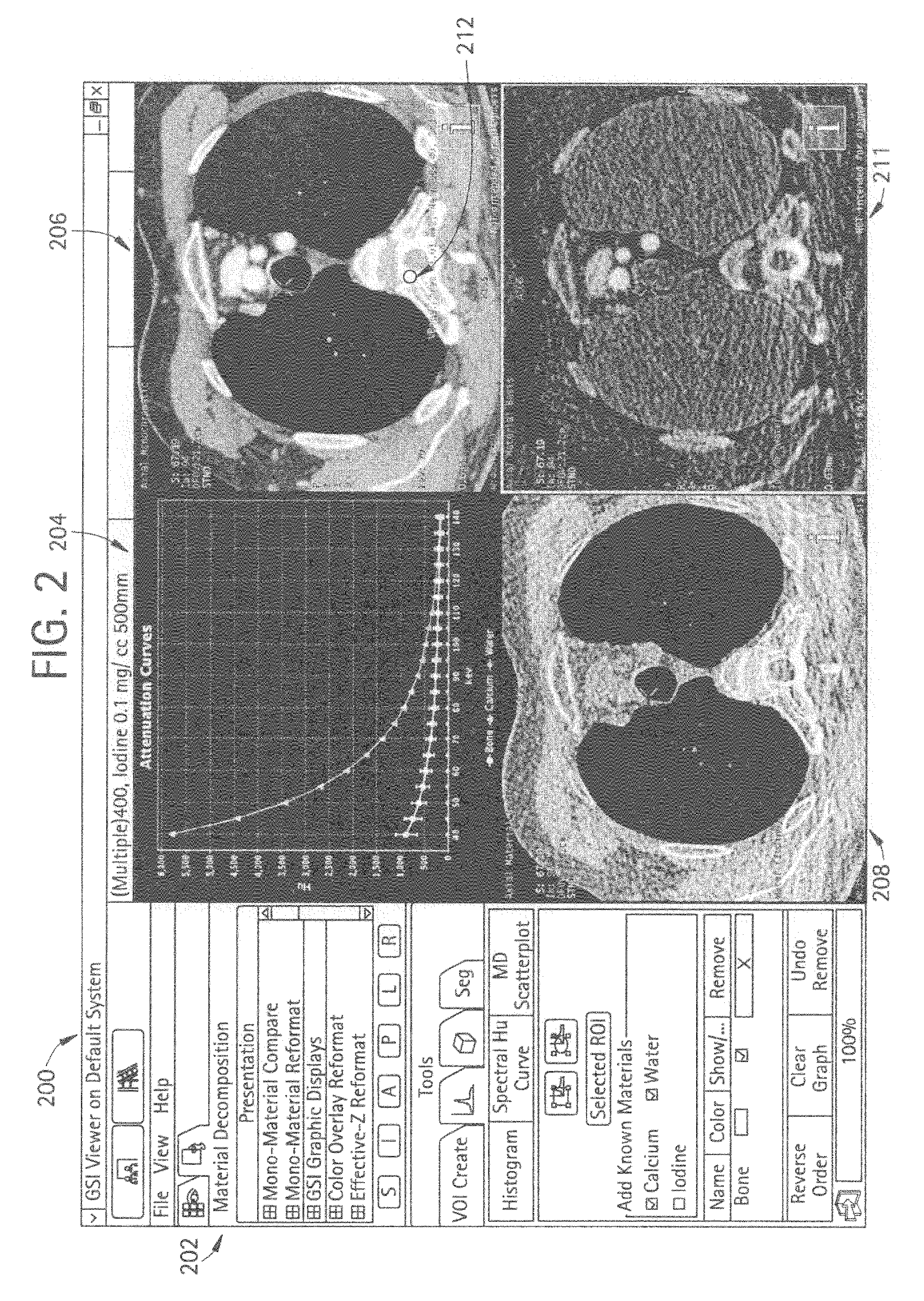
[0027]Certain embodiments of the present technology provide systems, methods and computer instructions for displaying multi-energy data, such as dual energy data, for example. Certain multi-energy data can be used in spectral imaging systems, such as photon counting systems, for example. Dual energy data, which is a type of multi-energy data, can be embodied in monochromatic images, material density images and / or effective-Z images. While many of the embodiments described herein are discussed in connection with dual energy data, the inventions described herein are not limited to dual energy data embodiments and can be used in connection with other types of multi-energy data, as one skilled in the art will appreciate. While many of the embodiments discussed herein discuss material density images for water and iodine, material density images for other materials can also be used, as one skilled in the art will appreciate. While many of the embodiments discussed herein include a user in...


PUM


Abstract

Systems, methods and computer instructions for displaying multi-energy data are provided. Certain methods include: receiving multi-energy data from an operably connected data source; displaying the multi-energy data as an image via a graphical user interface; selecting a region of interest in the displayed image; and displaying information regarding the region of interest via the graphical user interface. Certain methods include: (1) displaying a graph that includes an attenuation line depicting radiodensity versus energy level; (2) displaying a material density graph of a region of interest and/or of results of segmenting a region of interest; and/or (3) displaying information in a window configured to be movable about an interface. Certain methods include: receiving multi-energy data from an operably connected data source; and displaying the multi-energy data as a fused image via a graphical user interface.

Description

RELATED APPLICATIONS[0001][Not Applicable]FEDERALLY SPONSORED RESEARCH OR DEVELOPMENT[0002][Not Applicable]MICROFICHE / COPYRIGHT REFERENCE[0003][Not Applicable]BACKGROUND OF THE INVENTION[0004]Typically, in computed tomography (CT) imaging systems, an x-ray source emits a fan-shaped or a cone-shaped x-ray beam toward a subject or object, such as a patient or a piece of luggage, positioned on a support. The beam, after being attenuated by the subject, impinges upon a detector assembly. The intensity of the attenuated x-ray beam received at the detector assembly is typically dependent upon the attenuation of the x-ray beam by the subject.[0005]In known third generation CT systems, the x-ray source and the detector assembly are rotated on a rotatable gantry portion around the object to be imaged so that a gantry angle at which the fan-shaped x-ray beam intersects the object constantly changes. The detector assembly is typically made of a plurality of detector modules. Data representing ...

Claims


Application Information

Patent Timeline
IPC IPC(8): G06F3/01G06F3/048
CPCA61B6/032G06F19/3406G06F19/321A61B6/482G16H40/63G16H30/20
Inventor LICATO, PAULOKERLUND, DARINGAUTHAM, SARDAR MALTHOMSEN, BRIANGABRIELSE, BRADLEY
Owner GENERAL ELECTRIC CO
Why Eureka
Try Eureka