Hacksaw with Blade Tensioning Mechanism

a technology of tensioning mechanism and hacksaw, which is applied in the field of hacksaws, can solve the problems of affecting the use of hacksaw, difficult to maintain a relatively constant tension of blades, and difficult to change blades with some prior art mechanisms, etc., and achieves simple, effective and/or safe blade tensioning and blade changes, and prevents vertical movement

Active Publication Date: 2010-06-03
BLACK & DECKER INC
View PDF99 Cites 26 Cited by
  • Summary
  • Abstract
  • Description
  • Claims
  • Application Information

AI Technical Summary

Benefits of technology

[0014]One advantage of the hacksaw of the present invention is that it provides a tensioning mechanism that can allow for simple, effective, and / or safe blade tensioning and blade changes. Another advantage of the hacksaw of the present invention is that the tensioning lever is rotatable to adjust the tension applied to the blade, but is substantially prevented from vertical movement when rotated. A further advantage of a currently preferred embodiment of the present invention is that the hacksaw includes a hollow I-beam frame that permits blade storage therein while maintaining a relatively rigid frame in comparison to the above-described prior art hollow hacksaw frames.

Problems solved by technology

However, changing blades with some prior art mechanisms can be a relatively time consuming and / or difficult procedure.
In addition, it can be difficult to maintain a relatively constant tension in the blades.
Another drawback is that some prior art blade tensioning mechanisms include tensioning levers for tensioning the hacksaw blades that translate vertically with respect to the hacksaw frame when manipulated and, in turn, tend to interfere with the use of the hacksaw and / or become damaged.
One drawback associated with some such blade tensioning mechanisms is that the blades tend to pop off or otherwise disconnect from the blade mounts during blade changes.
A further drawback is that some prior art hacksaws do not provide storage for extra blades, and, those which do, tend to do so in a manner that may structurally weaken the elongate top frame arm and / or provide a hacksaw frame that is less rigid than otherwise desired.

Method used


Image

  • Hacksaw with Blade Tensioning Mechanism
  • Hacksaw with Blade Tensioning Mechanism
  • Hacksaw with Blade Tensioning Mechanism

Examples


Embodiment Construction

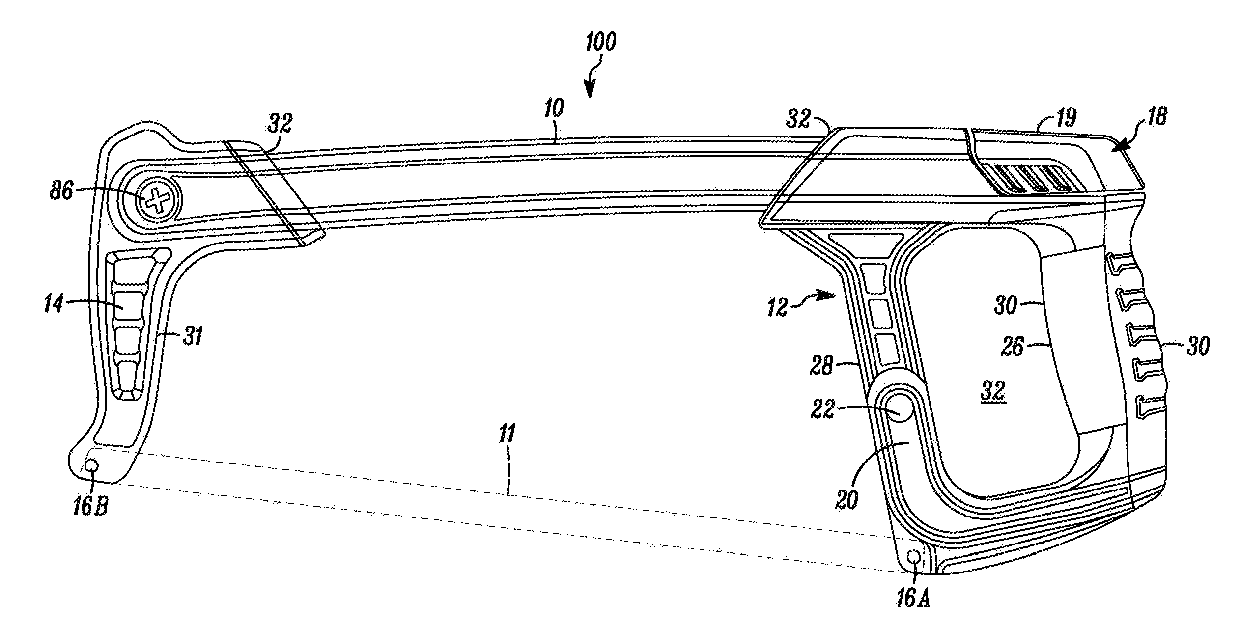
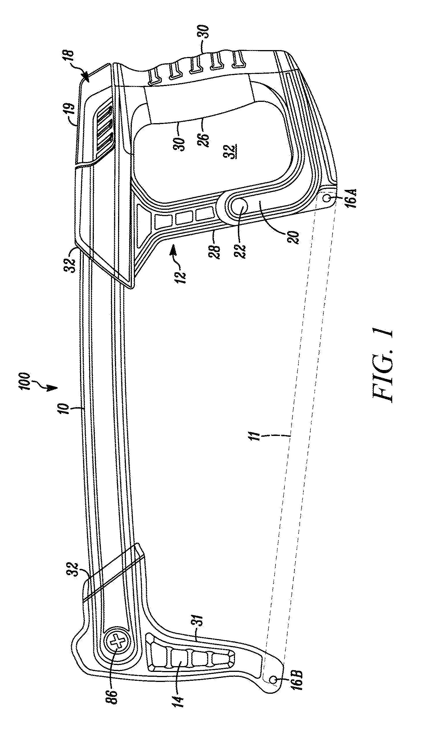
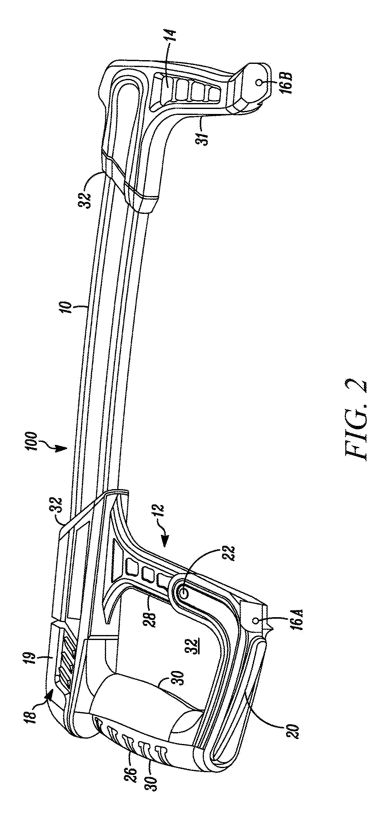
[0030]In FIGS. 1 and 2, a hacksaw embodying the present invention is indicated generally by the reference numeral 100. The hacksaw 100 is usable with elongate blades to cut workpieces. As shown in FIGS. 1 through 3, the hacksaw 100 comprises a frame including an elongate top frame arm 10, a proximal handle 12 fixedly secured to the proximal end of the top frame arm 10, and a distal handle and blade mount 14 fixedly secured to the distal end of the top frame arm 10. The proximal handle 12 includes a proximal blade mount 16A for mounting thereto one end of a blade 11 (shown in broken lines in FIG. 1), and the distal handle and blade mount 14 includes a distal blade mount 16B for mounting thereto the other end of the blade 11. The proximal handle 12 includes a blade tensioning assembly 18 for adjusting the tension applied to the blade 11 mounted to the blade mounts 16A, 16B. The blade tensioning assembly 18 includes a manually engageable blade tensioning lever 19 that is rotatably moun...


PUM

PropertyMeasurementUnit
radiusaaaaaaaaaa
radiusaaaaaaaaaa
width W2aaaaaaaaaa

Abstract

A hacksaw with an improved mechanism for applying and adjusting the tension on a blade mounted to a blade mount on a front arm and a blade mount on a rocker arm. The rocker arm is pivotally coupled to a handle and is spring biased to place an initial tension on a blade held by the rocker arm and the front arm. A rotatably mounted lever is positioned on the handle for vertically displacing a nut captured in the rocker arm to pivot the rocker arm and adjust the tension on the rocker arm-held blade. An elongate top frame bar of the hacksaw defines a hollow I-beam cross-section accessible from the face of the front handle and is capable of storing saw blades. A bale screw is positioned in the front member for securing the blades in a position extending past the front handle.

Description

CROSS-REFERENCE TO RELATED APPLICATION[0001]This application claims priority to similarly titled U.S. Patent Application No. 61 / 118,573, filed Nov. 28, 2008, the contents of which is expressly incorporated by reference in its entirety as part of the present disclosure.FIELD OF THE INVENTION[0002]The present invention relates generally to hacksaws and, more particularly, to hacksaws with mechanisms for maintaining and adjusting the tension in hacksaw blades and / or hacksaws with hollow frames that may be used for storage of spare blades.BACKGROUND[0003]Conventional hacksaws include a frame with three main elements: a proximal handle, a distal handle, and an elongate top frame arm extending between the proximal and distal handles. The proximal and distal handles include blade mounts vertically spaced from the elongate top frame arm so that a hacksaw blade can be releasably coupled between the handles and define a usable cutting edge. Typically, one of the blade mounts is fixed while th...

Claims


Application Information

Patent Timeline
Patent Type & Authority Applications(United States)
IPC IPC(8): B27B21/06
CPCB23D51/125B23D49/12
Inventor GREEN, MATTHEWNOVAK, JOSEPHWEREMCHUK, PETER
Owner BLACK & DECKER INC
Why Eureka
Try Eureka