Reinforcement device for compression buckling strength and method of fastening the same

a technology of compression buckling strength and reinforcement device, which is applied in the direction of lighting support device, candle holder, spatial arrangement/disposition of cables, etc., can solve the problems of consuming considerable time and expense, and the succession of angle steel frame members is liable to fall in succession, so as to improve the compression buckling strength

Active Publication Date: 2010-06-03
KOREA ELECTRIC POWER CORP
View PDF17 Cites 9 Cited by
  • Summary
  • Abstract
  • Description
  • Claims
  • Application Information

AI Technical Summary

Benefits of technology

[0008]Therefore, the present invention is directed to solving the above and other problems of the related art, and an aspect of the invention is to provide a reinforcement device for compression buckling strength and a method of fastening the same, which can improve compression buckling strength in a detachable manner without power interruption of transmission lines, member disassembly or field preparation, so as to prevent an angle-type steel-frame member for a steel-frame structure or a steel power-transmission tower from undergoing compression buckling and accidental eccentricity.

Problems solved by technology

However, since the angle-type steel-frame members are vulnerable to compression buckling and accidental eccentricity, the angle-type steel-frame members are liable to fall in succession if an unexpected typhoon, strong wind or the like causes any one member to buckle.
However, for the steel power-transmission tower, these methods have problems in that many processes such as stoppage of power supply, member disassembly, preparation for reinforcement, and so on are needed.
Further, conventional reinforcement operation for the angle-type steel-frame member requires various preceding operations, such as transmission line bypass, working diagram preparation, work-plan establishment, and the like, which consume considerable time and expenses.

Method used


Image

  • Reinforcement device for compression buckling strength and method of fastening the same
  • Reinforcement device for compression buckling strength and method of fastening the same
  • Reinforcement device for compression buckling strength and method of fastening the same

Examples


Embodiment Construction

[0028]Hereinafter, exemplary embodiments of the present invention will be described in more detail with reference to FIGS. 2 to 6.

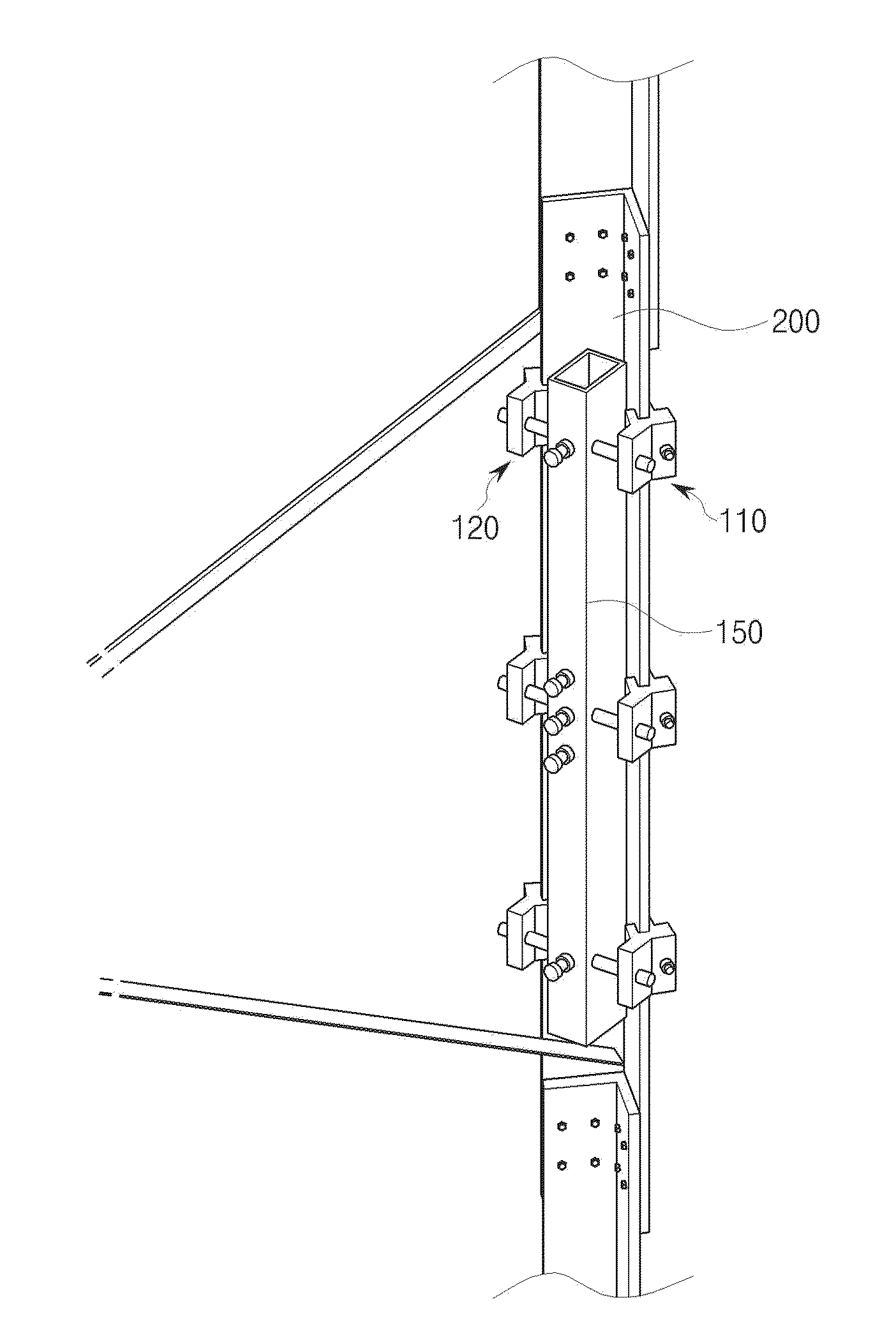
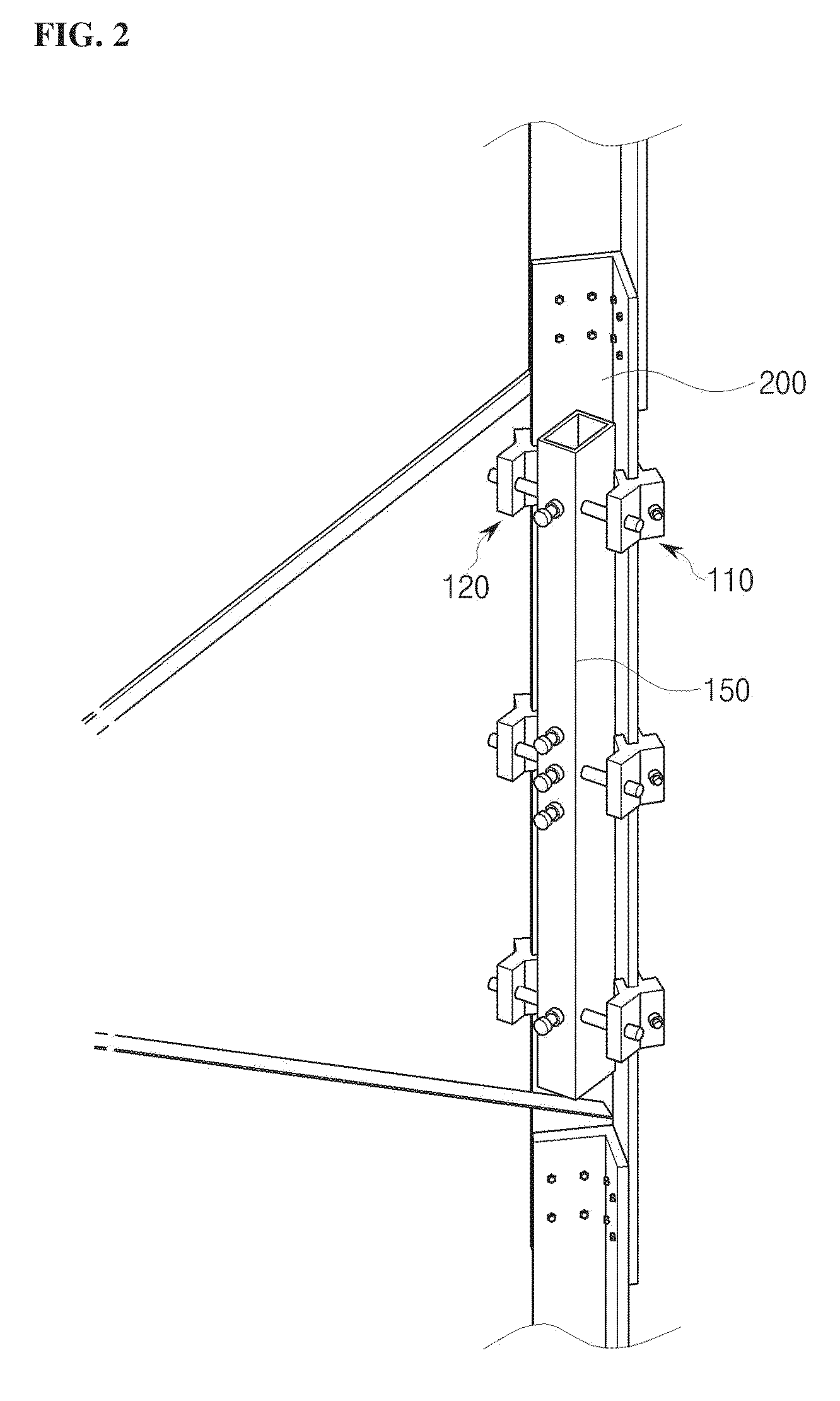
[0029]FIG. 2 is a perspective view of an angle-type steel-frame member provided with a reinforcement device for compression buckling strength according to one embodiment of the invention, and FIG. 3 is a detailed sectional view of the reinforcement device of FIG. 2.

[0030]In general, a steel power-transmission tower has a truss structure, which is designed to connect steel-frame members triangularly and use tension and compressive force of the members to resist external force. The truss structure is believed to be effective against earthquakes since it enables construction of a lightweight and rigid structure. Here, an angle-type steel-frame member 200 is employed as the steel-frame member for the steel power-transmission tower having the truss structure and is also employed as a brace for resisting lateral force in a steel-frame structure. Further, the an...


PUM


Abstract

A reinforcement device for compression buckling strength and a method of fastening the same are disclosed. The reinforcement device includes a member seating body surrounding an angle-type steel-frame member, first and second securing couplers securing opposite ends of the angle-type steel-frame member and opposite ends of the member seating body and adjustable to meet a standard of the angle-type steel-frame member, a horizontal engaging element connecting the first and second securing couplers with each other, a supporter positioned in a space where the angle-type steel-frame to member forms a right angle and supporting the angle-type steel-frame member, and a reinforcing bar connecting the supporter and the horizontal engaging element. The reinforcement device prevents an angle-type steel-frame member for a steel-frame structure or a steel power-transmission tower from undergoing compression buckling and accidental eccentricity, and improves compression buckling strength without power interruption of transmission lines, member disassembly, or field preparation.

Description

BACKGROUND OF THE INVENTION[0001]1. Field of the Invention[0002]The present invention relates to a reinforcement device for compression buckling strength and a method of fastening the same, which can improve compression buckling strength in a detachable manner, without power interruption of transmission lines, member disassembly or field preparation, so as to prevent an angle-type steel-frame member for a steel-frame structure or a steel power-transmission tower from undergoing compression buckling and accidental eccentricity.[0003]2. Description of the Related Art[0004]In general, a steel power-transmission tower has a truss structure, which is designed to connect steel-frame members triangularly and use tension and compressive force of the members to resist external force. Since the truss structure enables construction of a lightweight and rigid structure, it is believed to be effective against earthquakes. Here, an angle-type steel-frame member is employed not only as the steel-f...

Claims


Application Information

Patent Timeline
Patent Type & Authority Applications(United States)
IPC IPC(8): E04B1/21E04B1/38F16B7/04
CPCE04C3/32Y10T403/1624E04H12/10E04G23/0218E04H12/2292H02G7/14H02G7/20
Inventor KIM, KANG SIKKWON, KI JOO
Owner KOREA ELECTRIC POWER CORP
Why Eureka
Try Eureka