Reading circuit for a multi-axis MEMS gyroscope having detection directions inclined with respect to the reference axes, and corresponding multi-axis MEMS gyroscope

a multi-axis, mems gyroscope technology, applied in the direction of acceleration measurement using interia force, speed measurement using gyroscopic effects, devices using electric/magnetic means, etc., can solve the problem that the reading circuit previously described is not usable in the cas

Active Publication Date: 2010-06-03
STMICROELECTRONICS SRL
View PDF41 Cites 60 Cited by
  • Summary
  • Abstract
  • Description
  • Claims
  • Application Information

AI Technical Summary

Benefits of technology

[0017]One embodiment is a reading circuit that is able to operate in the case where the detection directions of the sensor are inclined with respect to the corresponding reference axes (for example, the axes of pitch and roll).

Problems solved by technology

The present Applicant has found that the reading circuit previously described is not, however, usable in the case where the multi-axis gyroscope has detection directions that do not coincide with its reference axes, being for example inclined by a given angle with respect to the reference axes.

Method used


Image

  • Reading circuit for a multi-axis MEMS gyroscope having detection directions inclined with respect to the reference axes, and corresponding multi-axis MEMS gyroscope
  • Reading circuit for a multi-axis MEMS gyroscope having detection directions inclined with respect to the reference axes, and corresponding multi-axis MEMS gyroscope
  • Reading circuit for a multi-axis MEMS gyroscope having detection directions inclined with respect to the reference axes, and corresponding multi-axis MEMS gyroscope

Examples


first embodiment

[0053]In detail, FIG. 4 (where elements that are similar to others already described previously are designated by the same reference numbers and will not be described in detail again) shows a reading circuit 30 according to the present disclosure, where the aforesaid combination stage, designated by 32, is set upstream of the entire transduction chain (i.e., upstream of the charge amplifier 2 of the measurement chain for DSB-SC signals), and has inputs directly connected to the electrodes of the MEMS structure 10.

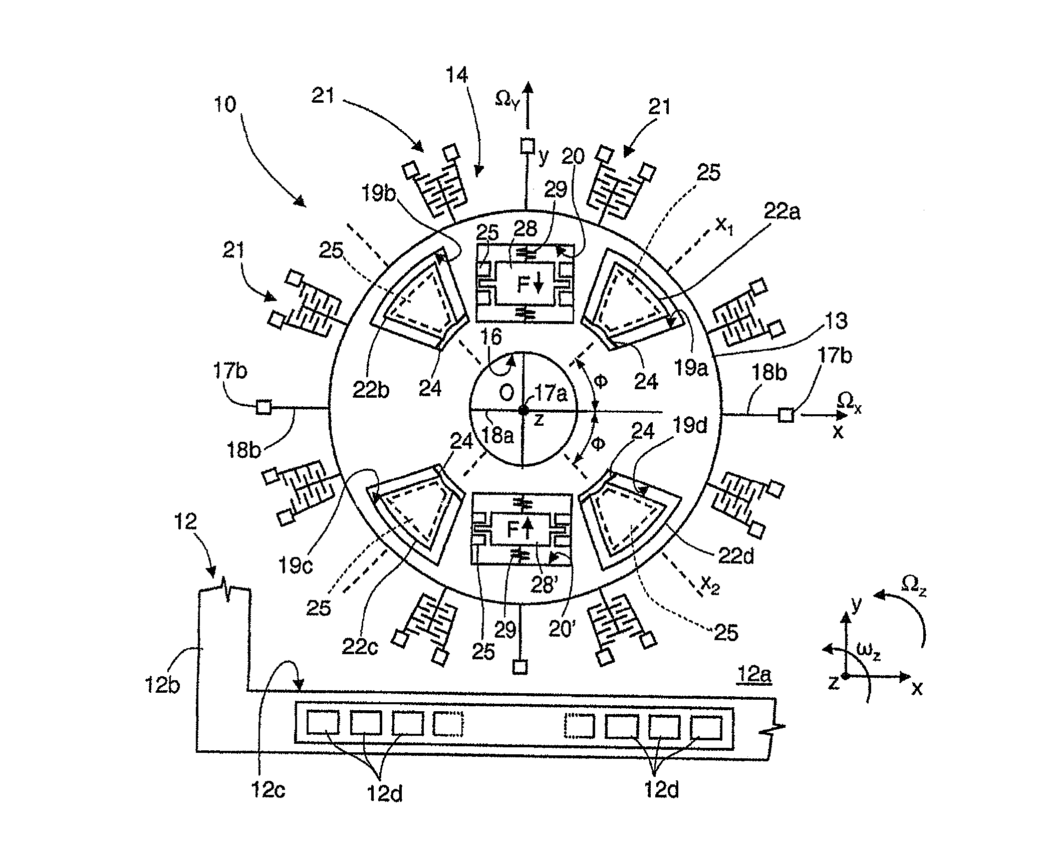
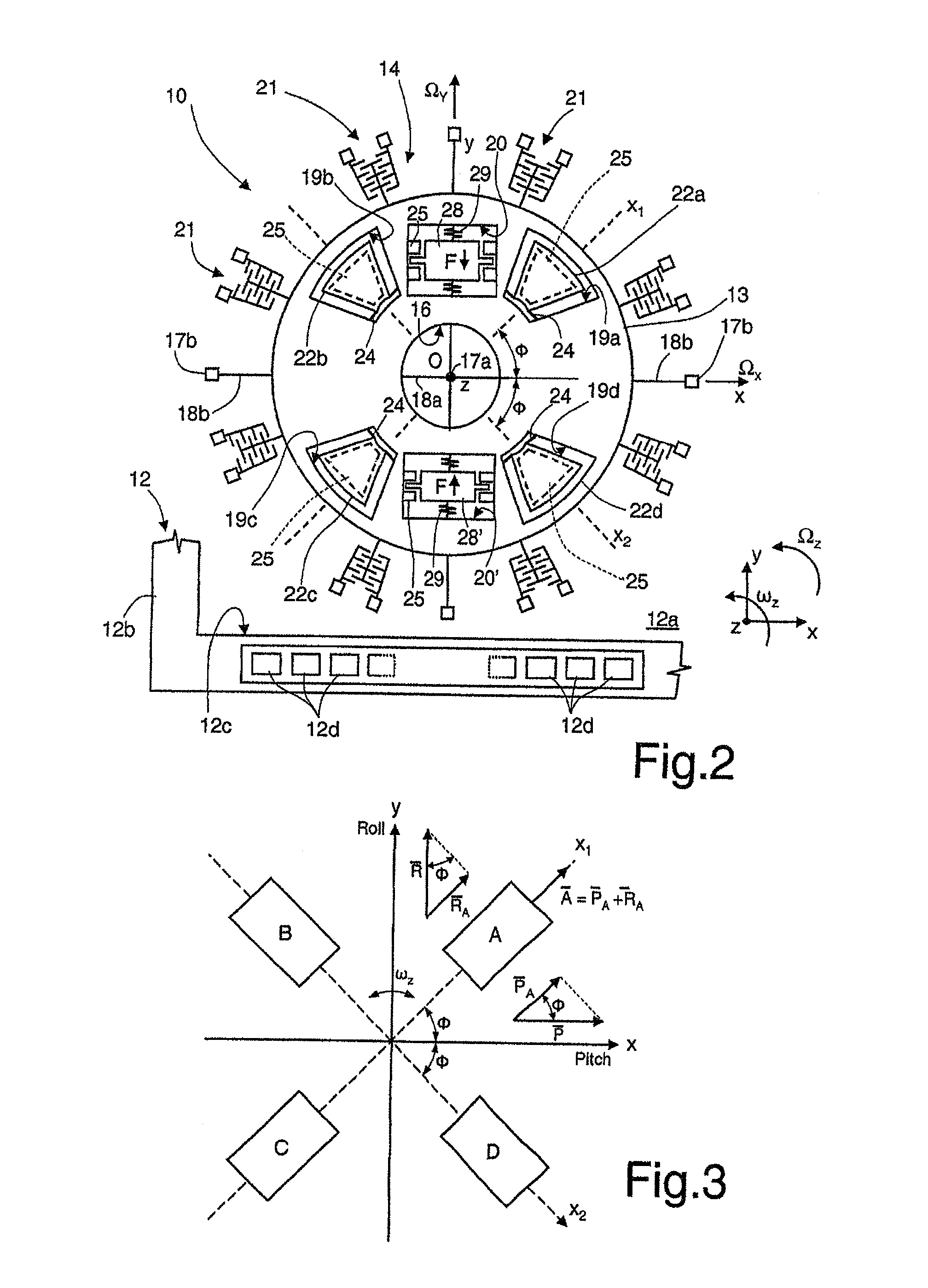
[0054]In a way similar to what is illustrated in FIG. 3, the fixed electrodes corresponding to the sensing masses 22a-22d are designated by A, B, C and D, on the hypothesis that associated to each of the sensing masses is a single fixed electrode; again illustrated are also the sensing capacitors with opposite capacitive variations formed between the fixed electrodes of sensing masses aligned in a same detection direction x1, x2, and the common mobile electrode Rot (the mob...

second embodiment

[0067]the reading circuit, here designated by 30′ (see FIG. 6) hence envisages the use of two distinct measurement chains for the DSB-SC signals, designated by 40a, 40b (or possibly, in a way not illustrated, of three distinct measurement chains, in the case of a triaxial gyroscope), respectively for the DSB-SC signals corresponding to the angular velocities of pitch and roll, each chain comprising a respective charge amplifier 2 and a respective demodulator 4, cascaded together.

[0068]The combination stage, here designated by 32′, is positioned downstream of the demodulators 4 of the two measurement chains for DSB-SC signals 40a, 40b, and has its inputs connected to the differential outputs of the same demodulators 4.

[0069]In greater detail, the first measurement chain for DSB-SC signals, designated by 40a, is connected at input to the fixed electrodes A and C and acquires and processes jointly the capacitive contributions associated to the sensing masses 22a and 22c of the first pa...


PUM


Abstract

A multi-axis gyroscope includes a microelectromechanical structure configured to rotate with respective angular velocities about respective reference axes, and including detection elements, which are sensitive in respective detection directions and generate respective detection quantities as a function of projections of the angular velocities in the detection directions. The gyroscope including a reading circuit that generates electrical output signals, each correlated to a respective one of the angular velocities, as a function of the detection quantities. The reading circuit includes a combination stage that combines electrically with respect to one another electrical quantities correlated to detection quantities generated by detection elements sensitive to detection directions different from one another, so as to take into account a non-zero angle of inclination of the detection directions with respect to the reference axes.

Description

BACKGROUND[0001]1. Technical Field[0002]The present disclosure relates to a reading circuit for a multi-axis MEMS gyroscope having detection directions inclined with respect to the reference axes, and to a corresponding multi-axis MEMS gyroscope.[0003]2. Description of the Related Art[0004]As is known, micromachining techniques enable manufacturing of microelectromechanical structures or systems (MEMS) within layers of semiconductor material, which have been deposited (for example, a polycrystalline-silicon layer) or grown (for example, an epitaxial layer) on sacrificial layers, which are removed via chemical etching.[0005]Inertial sensors, such as accelerometers and gyroscopes, made using this technology are experiencing an increasing success, for example in the automotive field, in inertial navigation, or in the sector of portable devices.[0006]In particular, integrated gyroscopes made of semiconductor material using MEMS technology are known. These gyroscopes operate on the basis...

Claims


Application Information

Patent Timeline
Patent Type & Authority Applications(United States)
IPC IPC(8): G01C19/56
CPCG01C19/56G01C19/5712
Inventor CAMINADA, CARLOPRANDI, LUCIANO
Owner STMICROELECTRONICS SRL
Why Eureka
Try Eureka