

Motor-Driven Bogie for a Streetcar
- Summary
- Abstract
- Description
- Claims
- Application Information
AI Technical Summary
Benefits of technology
Problems solved by technology
Method used
Image


Examples
first embodiment
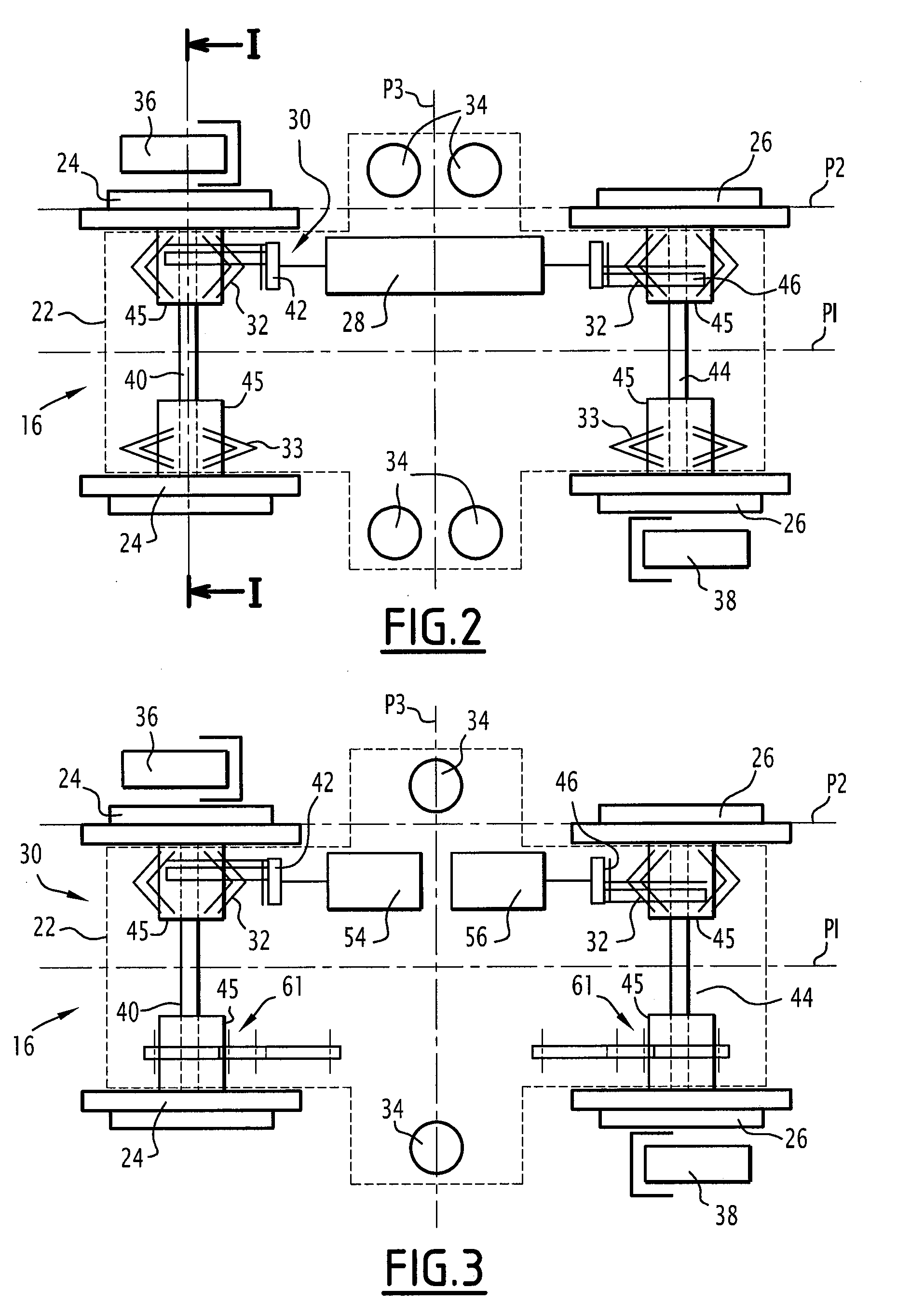
[0038]In the invention, each bogie comprises, as shown schematically in FIG. 2:[0039]a bogie chassis 22;[0040]two front wheels 24 and two rear wheels 26;[0041]a driving motor 28;[0042]transmission means 30 suitable for transmitting the torque generated by the motor 28 to the front wheels 24 and the rear wheels 26;[0043]primary suspension components 32 and 33, and secondary suspension components 34;[0044]front and rear brakes 36 and 38.
[0045]The chassis 22 typically comprises two longitudinal side members (not shown), and two transverse cross members (not shown) attached rigidly to one another. Only the outer contour of the chassis 22 is shown in FIG. 2. The contour is represented by dashed lines.
[0046]The front wheels 24 are coaxial, spaced transversely from one another, and are connected to the chassis 22. Similarly, the rear wheels 26 are coaxial, spaced transversely from one another, and connected to the chassis 22.
[0047]The front wheels 24 are spaced longitudinally from the rear...
second embodiment
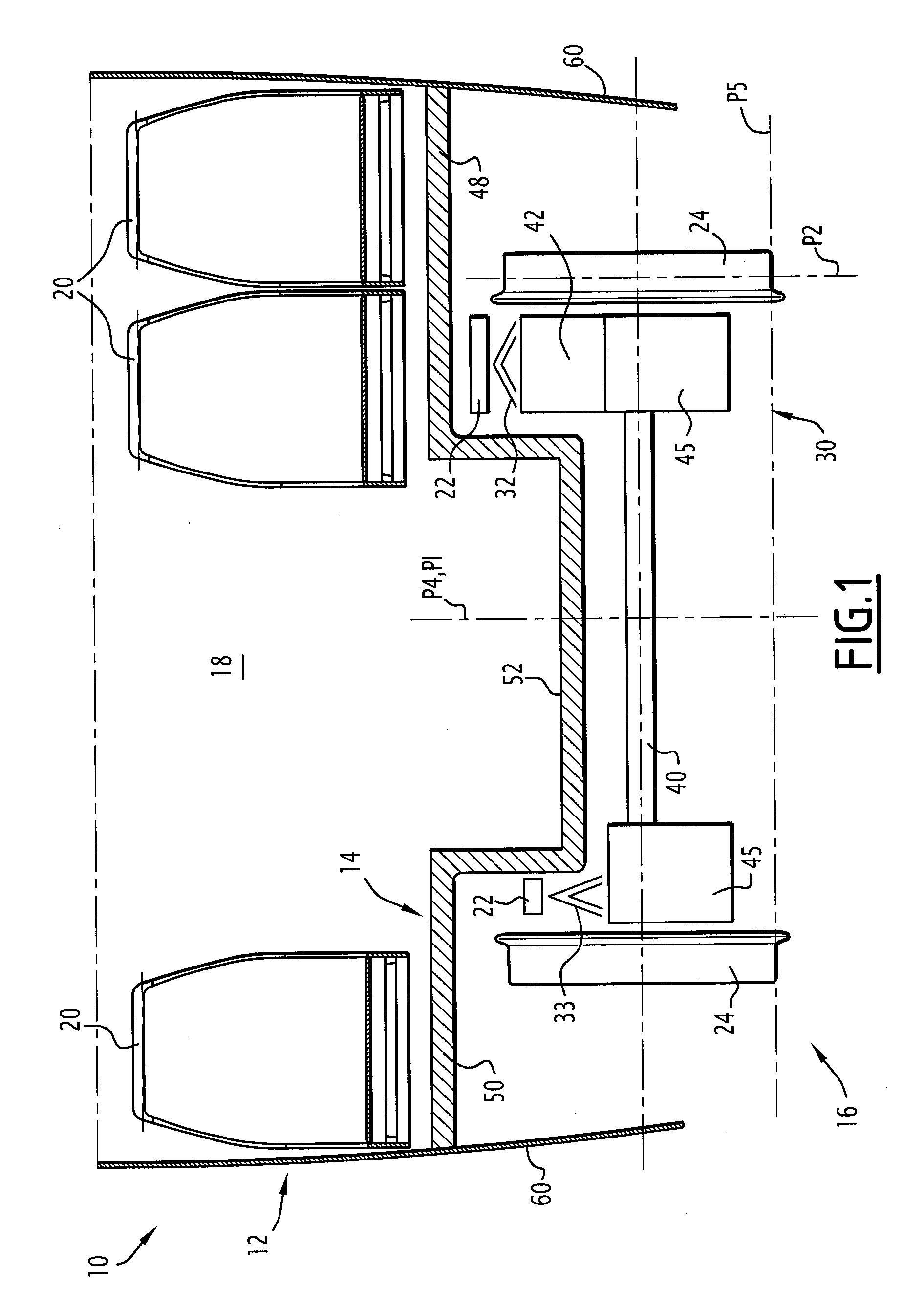
[0099]In the invention, the second raised portion 50 of the floor of the body 14 only covers the wheels 24 and 26 situated on the second side. The low primary suspension components 61 are placed below the circulation corridor 52, which is itself situated, relative to the rolling plane P5 of the bogie, at a level between 280 mm and 480 mm, preferably between 330 mm and 430 mm, and typically having a value of 380 mm.
[0100]In this casing, the circulation corridor extends, viewed in a plane perpendicular to the principal direction, virtually from the reducing gears 42 and 46 or the motor 28 to the wheels 24 and 26 situated on the second side. It is 900 mm wide in the casing of a non-pivoting bogie and 650 mm wide in the casing of a pivoting bogie.
[0101]The bogie and railway vehicle described above have many advantages.
[0102]Because the motor or motors are mounted on the chassis, the drive train for transmission between the motor or motors and the wheels is shorter and mechanically simpl...
PUM
 Abstract
Description
Claims
Application Information