Non-Pneumatic Tire

a technology of non-pneumatic tires and tyres, which is applied in the direction of wheels, non-inflatable tyres, vehicle components, etc., can solve the problem of not being able to achieve the effect of suppressing the buckling of the ground portion between the web spokes, and achieve the effect of suppressing the buckling of the ground portion

Inactive Publication Date: 2010-06-03
TOYO TIRE & RUBBER CO LTD
View PDF16 Cites 60 Cited by
  • Summary
  • Abstract
  • Description
  • Claims
  • Application Information

AI Technical Summary

Benefits of technology

[0012]Accordingly, an object of the present invention is to provide a non-pneumatic tire in which a fluctuation in a circumferential direction of tire rigidity is hard to be generated by a positional relationship between a spoke position and a center position of a ground surface, and a buckling of a ground portion between the spokes can be sufficiently suppressed.
[0026]Further, in accordance with the non-pneumatic tire of the present invention, since the outer coupling portions are divided in the tire width direction, are independent in the tire circumferential direction, and are provided so as to be shifted in the tire circumferential direction per zones divided in the tire width direction, the outer coupling portions which are shifted from each other in the tire circumferential direction can improve the rigidity of the outer annular portion between the outer coupling portions which are adjacent in the tire circumferential direction in the adjacent zone. Accordingly, it is possible to sufficiently suppress the buckling of the ground portion between the outer coupling portions (the spokes). Further, since the non-pneumatic tire in accordance with the present invention is provided with the intermediate annular portion mentioned above per zones which are divided in the tire width direction, the fluctuation in the circumferential direction of the tire rigidity becomes small in each of the zones.
[0027]Therefore, in accordance with the present invention, it is possible to provide the non-pneumatic tire in which the fluctuation in the circumferential direction of the tire rigidity is hard to be generated by the positional relationship between the spoke position and the ground surface center position, and it is possible to sufficiently suppress the buckling of the ground portion between the spokes.

Problems solved by technology

However, it has been known that the non-pneumatic tire described in Japanese Patent No. 3966895 has a similar structure to the non-pneumatic tire described in Japanese Unexamined Patent Publication No. 2005-500932, in the individual zone, and is not sufficient in an effect of suppressing the buckling of the ground portion between the web spokes.

Method used


Image

  • Non-Pneumatic Tire
  • Non-Pneumatic Tire
  • Non-Pneumatic Tire

Examples


example 1

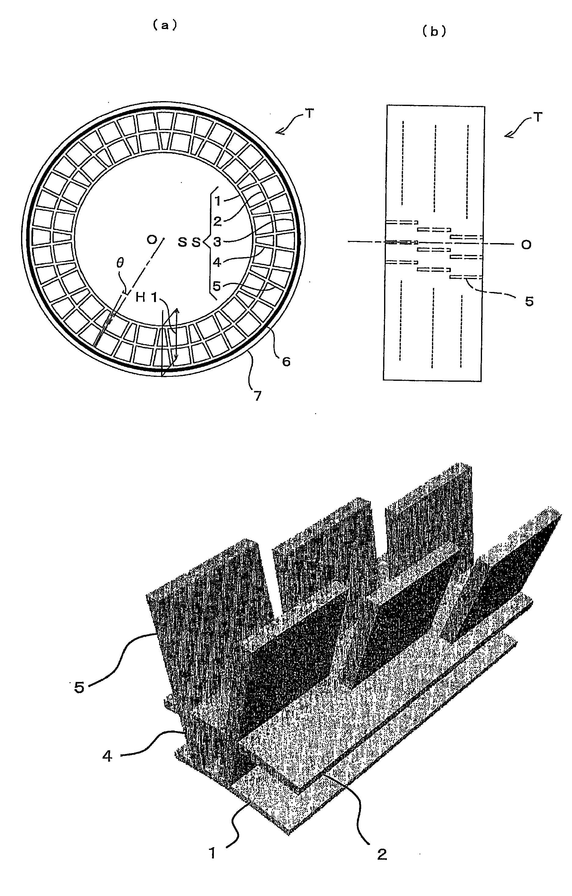
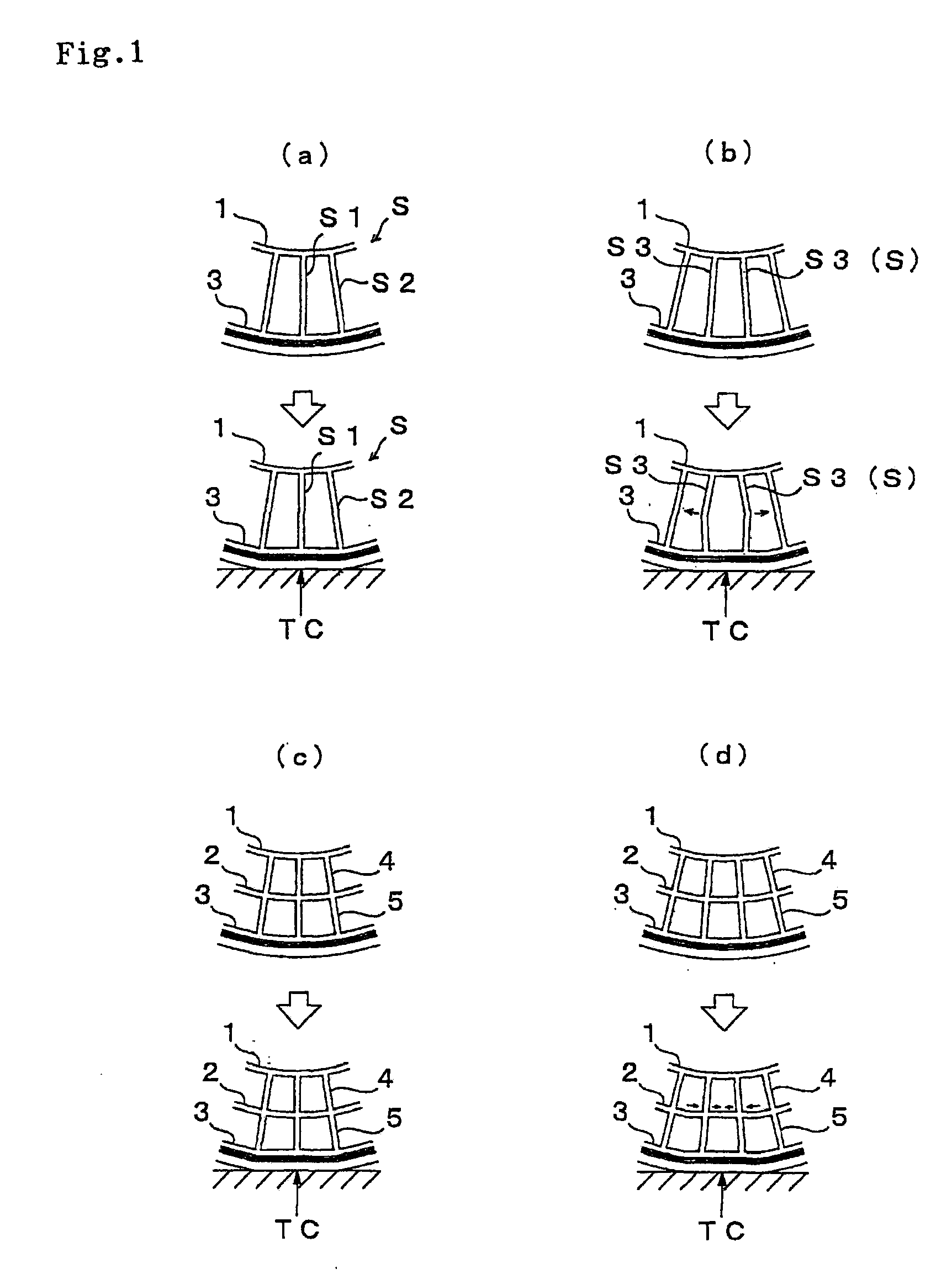
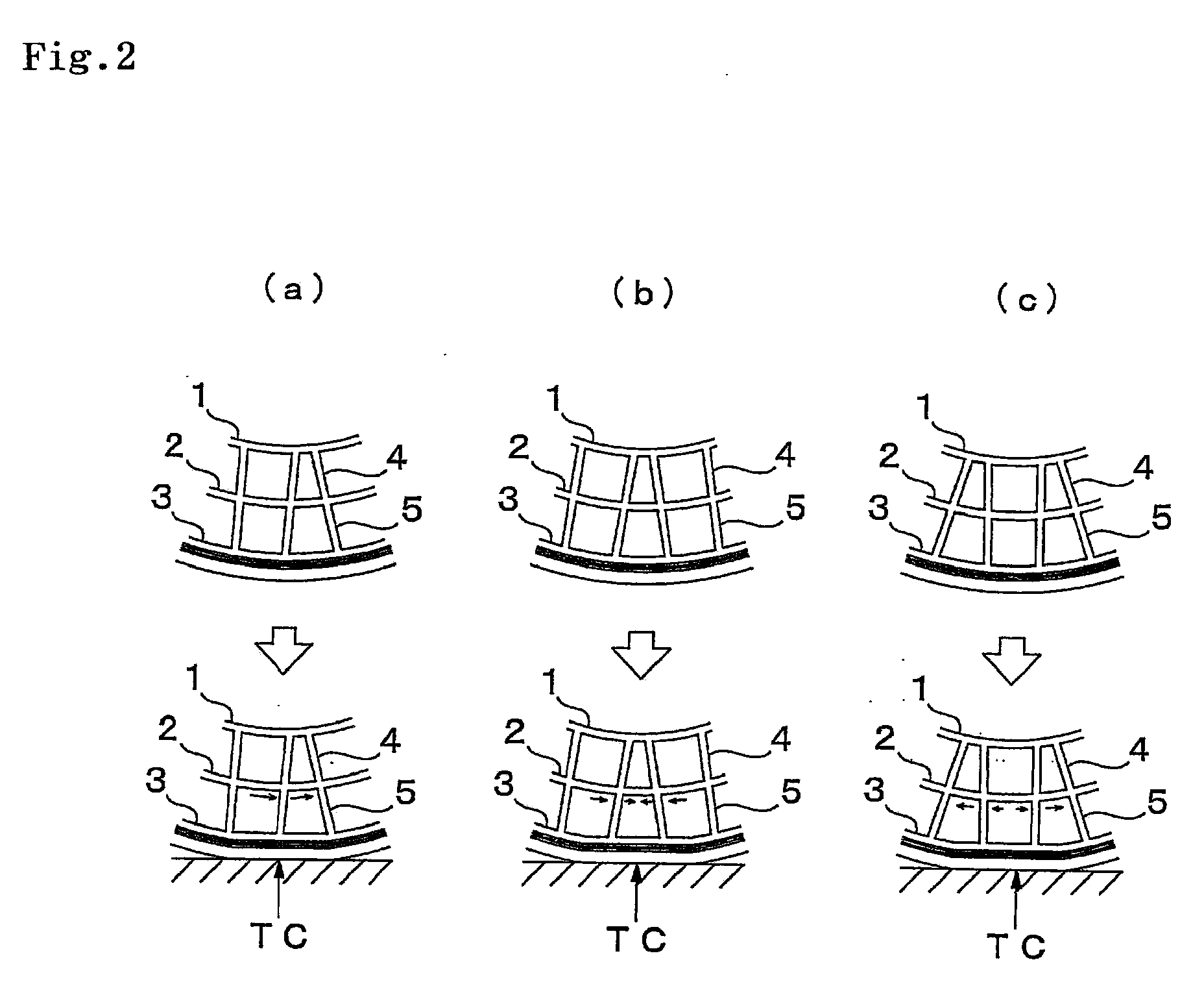
[0094]The performance mentioned above was evaluated by preparing a non-pneumatic tire having the support structure body provided with the inner ring (corresponding to the inner ring portion 1), the intermediate ring (corresponding to the internal annular portion 2), the outer ring (corresponding to the outer annular portion 3), the inner spoke (corresponding to the inner coupling portion 4), and the outer spoke (corresponding to the outer coupling portion 5), three layers of reinforcing layers provided in the outer periphery thereof, and the tread rubber in accordance with dimensions, physical properties and the like shown in Table 1. The inner spoke and the outer spoke are divided in the tire width direction, are independent in the tire circumferential direction, provided so as to be shifted from each other in the tire circumferential direction per zones which are divided in the tire width direction, and are shown as “with” phase displacement in Table 1. Results of the variance of ...


PUM


Abstract

The invention provides a non-pneumatic tire in which a fluctuation in a circumferential direction of tire rigidity is hard to be generated by a positional relationship between a spoke position and a center position of a ground surface, and a buckling of a ground portion between the spokes can be sufficiently suppressed. In a non-pneumatic tire T comprising a support structure body SS supporting a load from a vehicle, the support structure body SS includes an inner annular portion 1, an intermediate annular portion 2 concentrically provided in an outer side of the inner annular portion 1, an outer annular portion 3 concentrically provided in an outer side of the intermediate annular portion 2, a plurality of inner coupling portions 4 coupling the inner annular portion 1 and the intermediate annular portion 2, and a plurality of outer coupling portions 5 coupling the outer annular portion 3 and the intermediate annular portion 2, wherein the inner coupling portions 4 and the outer coupling portions 5 are divided in a tire width direction, are independent in a tire circumferential direction, and are provided so as to be shifted from each other in the tire circumferential direction per zones which are divided in the tire width direction.

Description

BACKGROUND OF THE INVENTION[0001]1. Field of the Invention[0002]The present invention relates to a non-pneumatic tire provided with a support structure body supporting a load from a vehicle, serving as a tire structure member, and preferably relates to a non-pneumatic tire which can be used in place of a pneumatic tire.[0003]2. Description of the Related Art[0004]A pneumatic tire has a function of supporting a load, a performance of absorbing a shock from a ground surface, and a performance of transmitting a power (accelerating, stopping and direction changing performance), and is accordingly employed in various vehicles, particularly a bicycle, a motor cycle, an automobile and a truck.[0005]Particularly, these capabilities greatly have contributed to a development of the automobile and other motor vehicles. Further, the shock absorbing performance of the pneumatic tire is useful in a transportation cart for medical equipment and an electronic device, and for other intended uses.[00...

Claims


Application Information

Patent Timeline
Patent Type & Authority Applications(United States)
IPC IPC(8): B60C7/00
CPCB60C7/18Y10T152/10297B60C17/061B60C7/22
Inventor IWASE, MASANORISEGAWA, MASAHIRO
Owner TOYO TIRE & RUBBER CO LTD
Why Eureka
Try Eureka