
Electronic tag holder for capped bottle neck

Active Publication Date: 2010-06-03
B & G INT
View PDF38 Cites 25 Cited by
  • Summary
  • Abstract
  • Description
  • Claims
  • Application Information

AI Technical Summary

Problems solved by technology

One troublesome location to apply tags is to the outside surface of a tapered neck of the bottle.
While this is a desirous location to apply the tag, it is difficult to attach the tag and maintain the tag on the neck.

Method used


Image

  • Electronic tag holder for capped bottle neck
  • Electronic tag holder for capped bottle neck
  • Electronic tag holder for capped bottle neck

Examples


Embodiment Construction

[0015]The present invention provides a housing assembly for supporting electronic tag on the neck of a bottle.

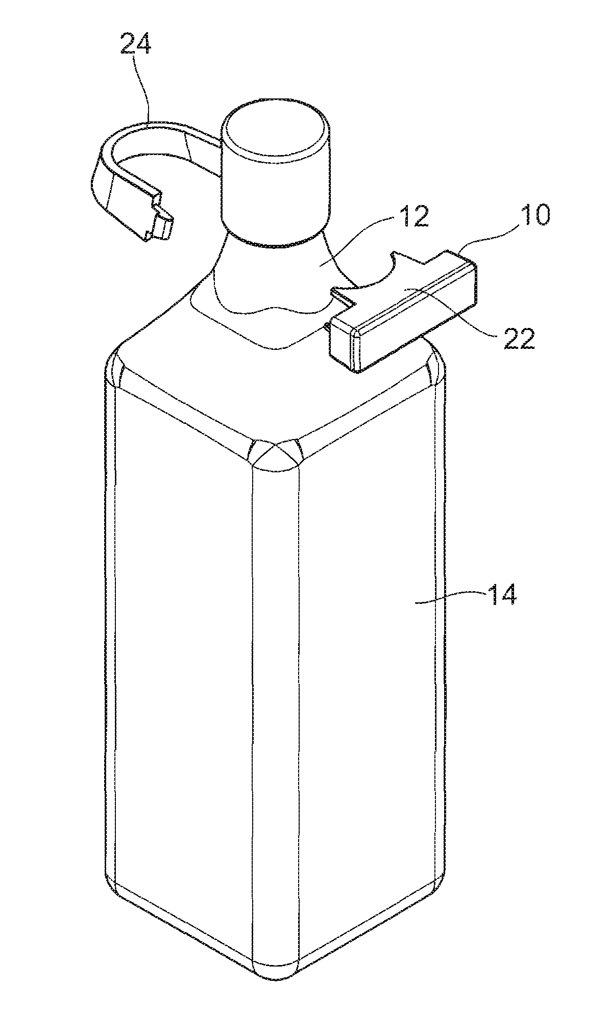
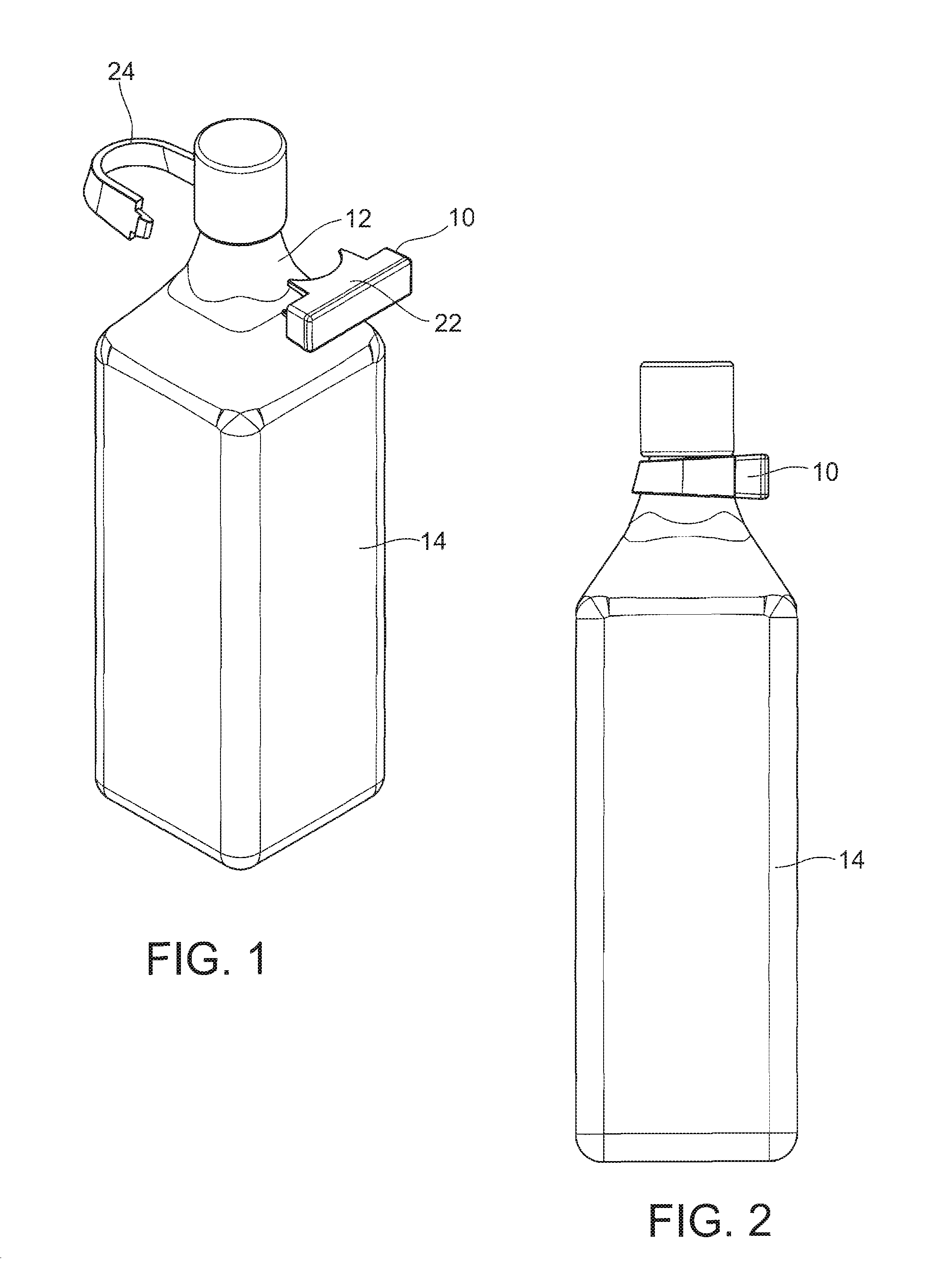
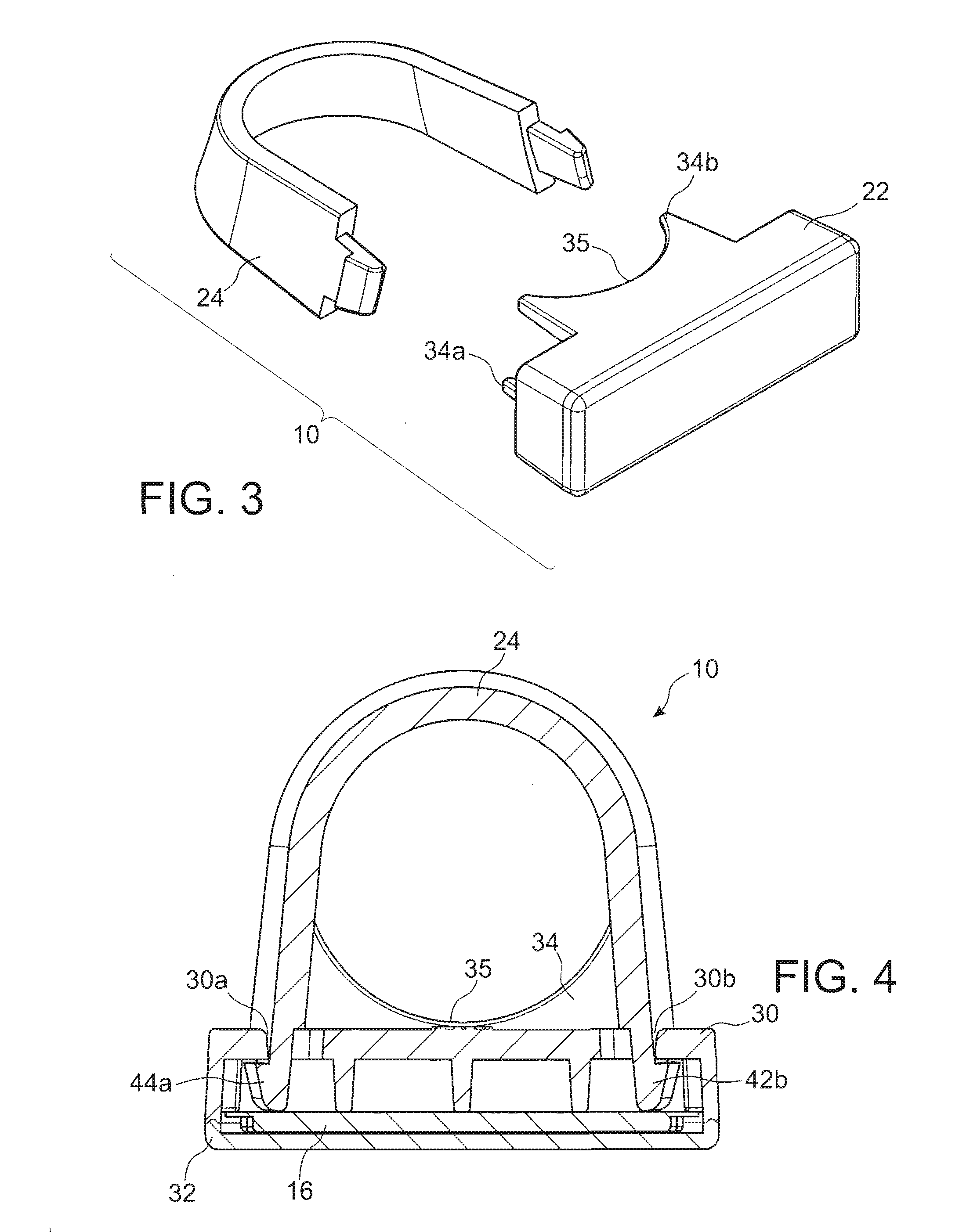
[0016]Referring to FIGS. 1 and 2, a tag housing assembly 10 may be supported on the neck 12 of a bottle 14. The tag housing assembly 16 includes a housing 22 and a strap 24 which is attachable to the housing 22 about the elongate extending neck 12 of bottle 14. Housing 22 as well as strap 24 may be formed of a suitable plastic material such as high impact polystyrene.

[0017]As shown in FIGS. 4 and 5, the housing assembly 10 supports an electronic tag 16 which may be a radio frequency identification (RFID) tag or an electronic article security tag (EAS) tag or any similar electronic tag. The present invention is designed to attach the electronic tag 16 to bottle 14 having a removable cap 20 (FIGS. 1 and 2) which prevents the tag housing 10 from being removed from the neck 12 of the bottle.

[0018]Referring now to FIG. 5, the housing 22 of the housing assembly 10 of the present i...


PUM


Abstract

A housing assembly supports an electronic tag to the extending neck of a bottle. The housing assembly includes a housing for accommodating the electronic tag. The housing has an annular bearing surface for engagement with the extending neck of the bottle. A strap is coupled to the housing about the bottle neck. The strap has a bearing surface for engagement with the extending neck where the bearing surface of the strap is tapered to match the taper of the extending neck of the bottle.

Description

CROSS-REFERENCE TO RELATED APPLICATION[0001]This application claims priority to U.S. Provisional Patent Application No. 61 / 119,484, filed on Dec. 3, 2008, which is incorporated herein by reference.FIELD OF THE INVENTION[0002]The present invention relates generally to a holder for an electronic tag. More particularly, the present invention relates to a holder for an electronic tag which may be applied to a capped bottle neck.BACKGROUND OF THE INVENTION[0003]Electronic tags are used for a wide variety of purposes, including the tracking of items which contain the tag, inventory control, security, and also provide information which may be electronically readable.[0004]These tags or markers may include radio frequency identification (RFID) tags or electronic article surveillance (EAS) tags. EAS tags may be used to provide theft deterrence. These tags are used in combination with an alarm system which monitors undesired movement of the article containing the EAS tag.[0005]Various housing...

Claims


Application Information

Patent Timeline
IPC IPC(8): B65D1/02H05K7/00
CPCB65D2203/10B65D2211/00G09F3/0323G09F2003/0273G09F3/16G09F23/06G09F3/0329F17C2205/058B65D23/14E05B73/0017
Inventor KOLTON, CHESTERNORMAN, MICHAELTETIYEVSKY, ALEX
Owner B & G INT
Learn More