Condition monitoring system for wind turbine generator and method for operating wind turbine generator

a condition monitoring and wind turbine technology, applied in the direction of electric generator control, machines/engines, mechanical equipment, etc., can solve the problems of inducing increased loads on the rotor and other drive train components,

Inactive Publication Date: 2010-06-03
GENERAL ELECTRIC CO
View PDF20 Cites 39 Cited by
  • Summary
  • Abstract
  • Description
  • Claims
  • Application Information

AI Technical Summary

Problems solved by technology

During operation of such known wind turbine generators, the rotor may experience a mass imbalance, thereby inducing increased loads on the rotor and other drive train components.
Also, the rotor's position with respect to the wind may induce increased loads on the rotor and other drive train components.

Method used


Image

  • Condition monitoring system for wind turbine generator and method for operating wind turbine generator
  • Condition monitoring system for wind turbine generator and method for operating wind turbine generator
  • Condition monitoring system for wind turbine generator and method for operating wind turbine generator

Examples


Embodiment Construction

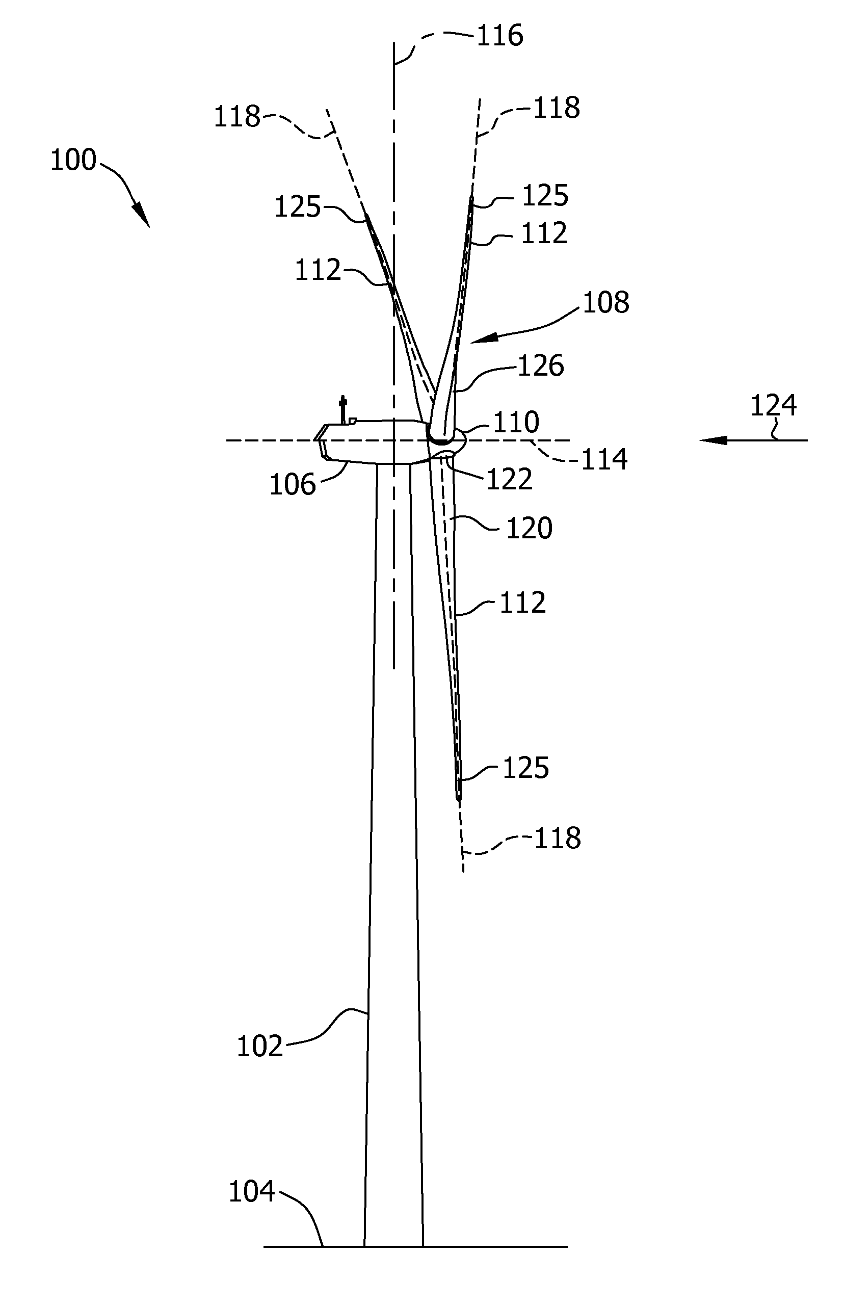
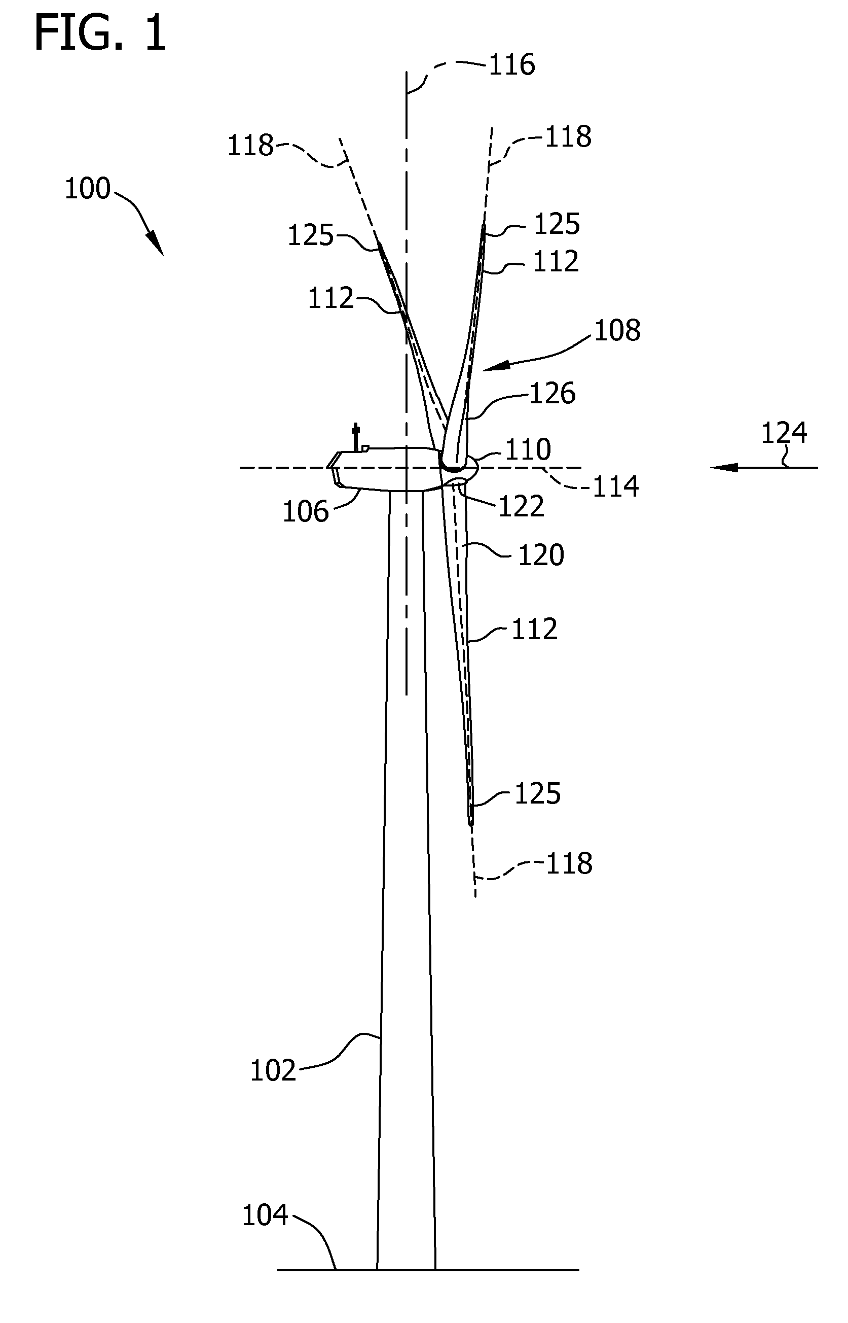
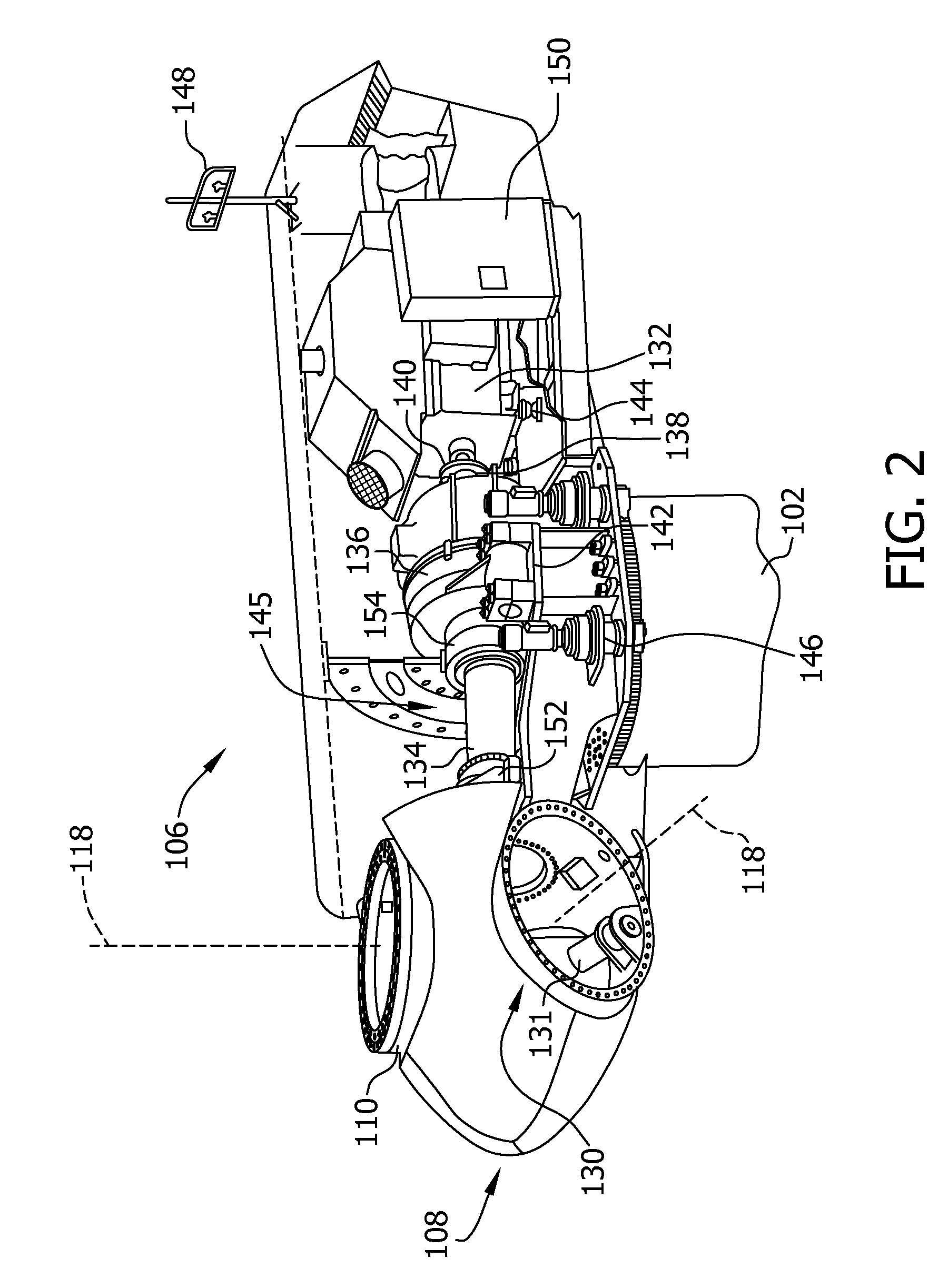
[0014]The method and condition monitoring system described herein facilitate operation of wind turbine generators by estimating a torque on a wind turbine rotor. Such rotor torque estimation provides indications of mass imbalances of, and increased stresses on, the wind turbine rotor that may be reduced by changes in blade pitch orientation and / or wind turbine yaw orientation. Reducing such stresses facilitates extending operational life expectancies of wind turbine drive train components.

[0015]A technical effect of the condition monitoring system and method described herein includes separating and isolating alternating torque (or oscillating torque) and constant torque (or static torque) from a free torque determination associated with a wind turbine generator. More specifically, a technical effect of the condition monitoring system and method described herein includes effectively separating free torque determinations into two components, that is, oscillating torque values and stat...


PUM


Abstract

A method for operating a wind turbine generator includes generating at least one of a plurality of rotor shaft angular displacement values, a plurality of rotor shaft angular velocity signals, and a plurality of rotor shaft angular acceleration signals. The method also includes determining a torsional moment within a rotor shaft, and modulating at least one of a wind turbine generator yaw orientation and a blade pitch orientation as a function of the determined torsional moment.

Description

BACKGROUND OF THE INVENTION[0001]The subject matter described herein generally relates to wind turbine generators and, more particularly, to a method and condition monitoring system for facilitating operation of wind turbine generators.[0002]At least some known wind turbine generators include a rotor having multiple blades. The rotor is sometimes coupled to a housing, or nacelle, that is positioned on top of a base, for example, a truss or tubular tower. At least some known utility grade wind turbines (i.e., wind turbines designed to provide electrical power to a utility grid) have rotor blades having predetermined shapes and dimensions. The rotor blades transform mechanical wind energy into induced blade lift forces that further induce a mechanical rotational torque that drives one or more generators via a drive train that includes a rotor shaft, subsequently generating electric power. The generators are sometimes, but not always, rotationally coupled to the rotor shaft through a g...

Claims


Application Information

Patent Timeline
Patent Type & Authority Applications(United States)
IPC IPC(8): H02P9/04
CPCF03D7/0204F03D7/0224F03D7/0292F03D7/042Y02E10/723F05B2270/1095F05B2270/309F05B2270/326F05B2270/327F05B2260/80Y02E10/72
Inventor STEGEMANN, KLAUSESSER, JUERGENFEHRENBACH, HERMANN R.
Owner GENERAL ELECTRIC CO
Why Eureka
Try Eureka