
Abnormal switching monitoring device and abnormal switching monitoring method

a monitoring device and abnormal switching technology, applied in power supply testing, instruments, electric lighting sources, etc., can solve problems such as increased switching loss, switch damage, power consumption increase by switching loss, and switch damag

Inactive Publication Date: 2010-06-03
FAIRCHILD KOREA SEMICON
View PDF9 Cites 24 Cited by
  • Summary
  • Abstract
  • Description
  • Claims
  • Application Information

AI Technical Summary

Benefits of technology

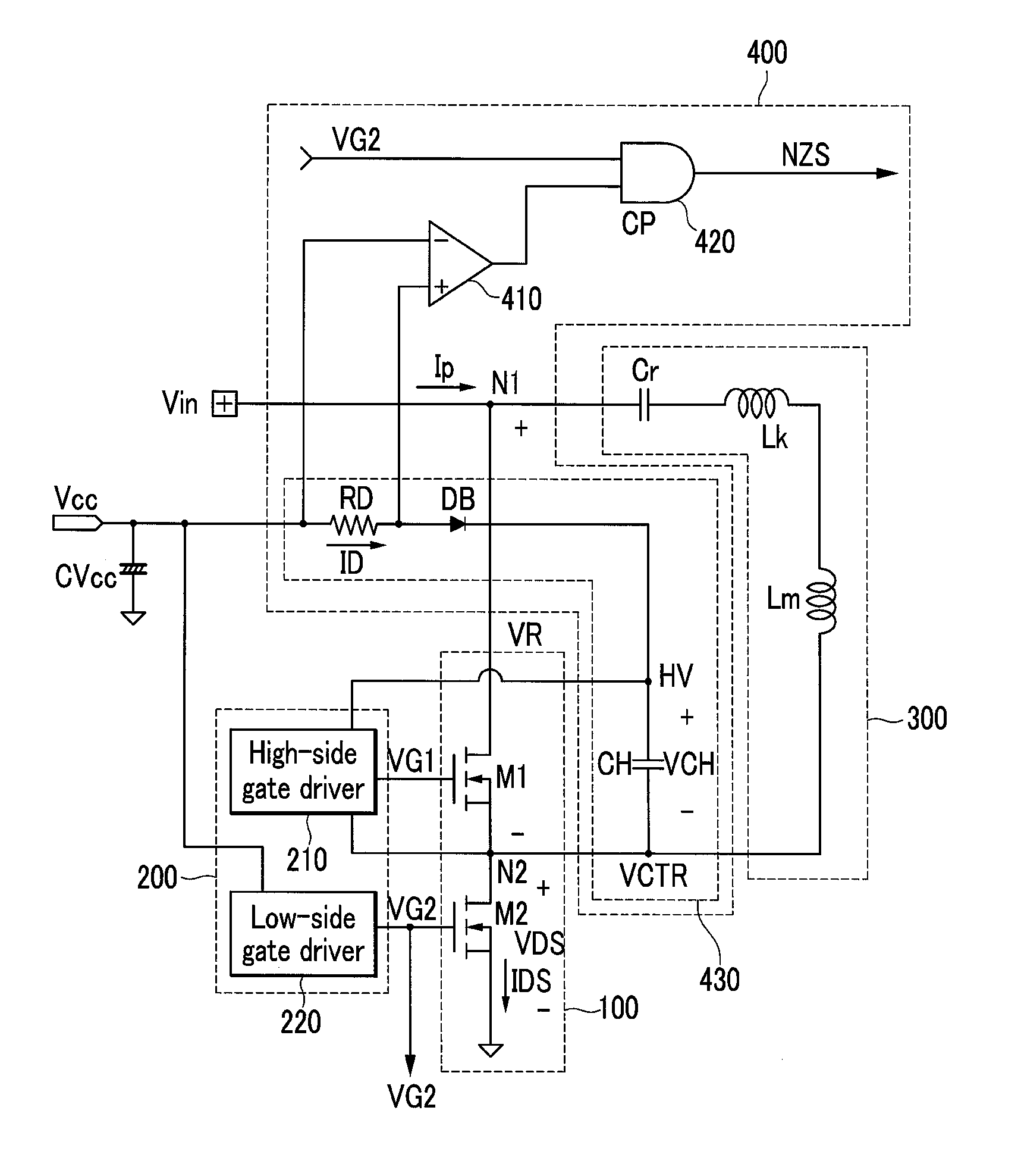
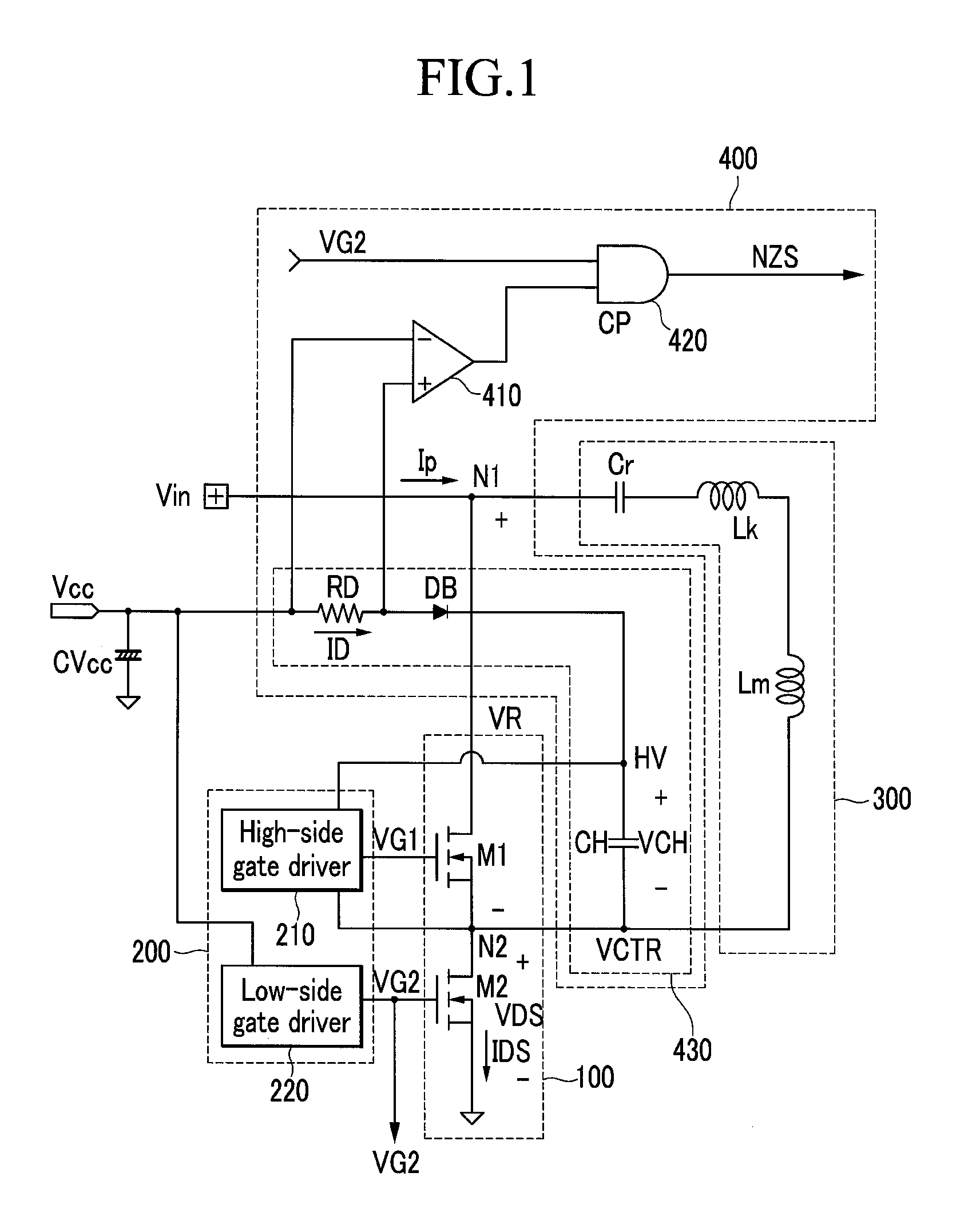
[0013]The abnormal switching monitoring device compares voltages of both ends of the current monitoring element with each other, and uses the comparison result and a low-side gate signal controlling the low-side switch so as to determine whether or not the non-zero voltage switching occurs. The abnormal switching monitoring device further includes a comparator including an inversion terminal connected to the first end of the current monitoring element and an non-inversion terminal connected to the second end of the current monitoring element, and an AND gate receiving an output signal of the comparator and a low-side gate signal. The abnormal switching monitoring device determines non-zero voltage switching in case a time point when the charge current begins to flow is later than a time point when the low-side switch is turned on.
[0014]Another exemplary embodiment of the present invention provides an abnormal switching monitoring device monitoring abnormal non-zero voltage switching of the high-side switch including a first electrode receiving an input voltage. The abnormal switching monitoring device includes a bootstrap circuit supplying an operating current to a gate driver controlling a switching operation of the high-side switch, and compares a time point when the current does not flow through the bootstrap circuit with a time point when the high-side switch is turned on so as to determine whether or not non-zero voltage switching of the high-side switch occurs.
[0015]The bootstrap circuit includes a bootstrap capacitor connected to the gate driver and supplying an operating current, a diode that makes the current flow to the bootstrap capacitor, and a current monitoring element including a first end to which the power source voltage is applied and a second end connected to the diode. The current monitoring element is a resistor. A first end of the bootstrap capacitor is connected to a cathode of the diode, a second end of the bootstrap capacitor is connected to a second electrode of the high-side switch, and an anode of the diode is connected to the second end of the current monitoring element.
[0016]The abnormal switching monitoring device compares voltages of both ends of the current monitoring element with each other, and uses the comparison result and a high-side gate signal controlling the high-side switch so as to determine whether or not the non-zero voltage s...

Problems solved by technology

Such phenomenon increases the switching loss.
In addition, it causes the switch to be damaged.
Accordingly, in case the switching when failing in the zero-voltage switching, that is, when the non-zero voltage switching occurs, a power consumption increase by switching loss and switch damage is caused.

Method used


Image

  • Abnormal switching monitoring device and abnormal switching monitoring method
  • Abnormal switching monitoring device and abnormal switching monitoring method
  • Abnormal switching monitoring device and abnormal switching monitoring method

Examples


Embodiment Construction

[0025]In the following detailed description, only certain exemplary embodiments of the present invention have been shown and described, simply by way of illustration. As those skilled in the art would realize, the described embodiments may be modified in various different ways, all without departing from the spirit or scope of the present invention. Accordingly, the drawings and description are to be regarded as illustrative in nature and not restrictive. Like reference numerals designate like elements throughout the specification.

[0026]Throughout this specification and the claims that follow, when it is described that an element is “coupled” to another element, the element may be “directly coupled” to the other element or “electrically coupled” to the other element through a third element. In addition, unless explicitly described to the contrary, the word “comprise” and variations such as “comprises” or “comprising” will be understood to imply the inclusion of stated elements but n...


PUM


Abstract

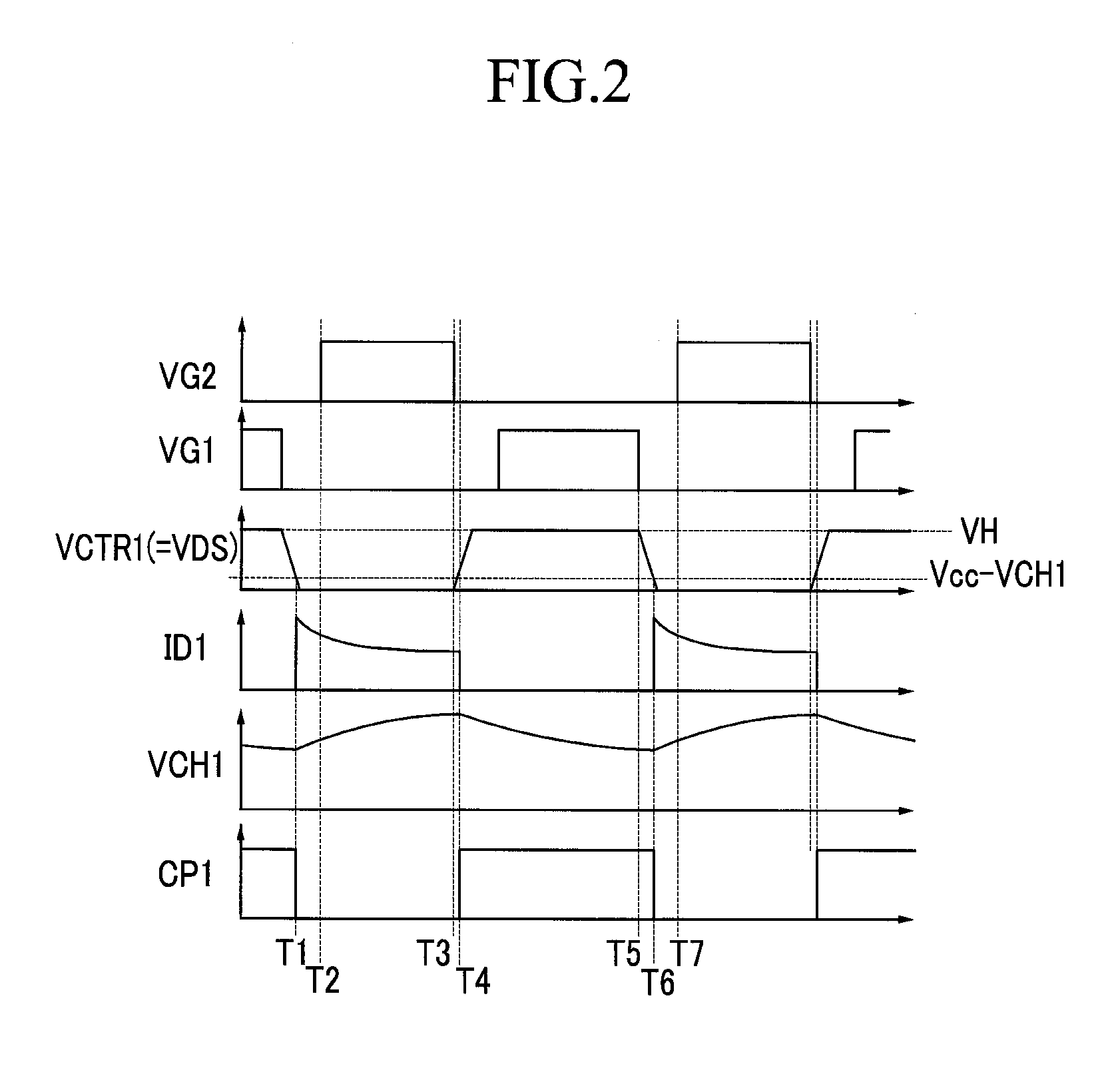
The present invention relates to an abnormal switching monitoring device and method. A time point when a high-side switch in which a first electrode receives an input voltage is turned on, a time point when a low-side switch that is connected to a second electrode of the high-side switch is turned on, a time point when a charge current begins to flow to a bootstrap circuit, and a time point when a charge current stops flowing to the bootstrap circuit are compared so as to determine whether or not non-zero voltage switching occurs. The bootstrap circuit supplies an operating current to a gate driver controlling a switching operation of the high-side switch.

Description

CROSS-REFERENCE TO RELATED APPLICATION[0001]This application claims priority to and the benefit of Korean Patent Application No. 10-2008-0119852 filed in the Korean Intellectual Property Office on Nov. 28, 2008, the entire contents of which are incorporated herein by reference.BACKGROUND OF THE INVENTION[0002](a) Field of the Invention[0003]The present invention relates to a monitoring device and method to detect an abnormal switching operation. Particularly, the present invention relates to a monitoring device to monitor non-zero voltage switching and a non-zero voltage switching method.[0004](b) Description of the Related Art[0005]It is preferable that a MOSFET switch controlling an operation of a converter is controlled in order to operate with zero voltage switching. The switching loss is reduced and damage to the switch can be prevented under the condition of the zero voltage switching. The zero voltage switching means that a voltage at both ends of the switch is “0” at the tur...

Claims


Application Information

Patent Timeline
IPC IPC(8): G01R19/00
CPCG01R31/3277H05B41/2856H02M1/36G01R31/40H02M1/32H02M3/155
Inventor EOM, HYUN-CHULKIM, JIN-TAEKOO, GWAN-BON
Owner FAIRCHILD KOREA SEMICON
Learn More