Domain Decomposition By the Advancing-Partition Method for Parallel Unstructured Grid Generation

a grid generation and domain decomposition technology, applied in the field of computational fluid dynamics, can solve the problems of increasing the difficulty of generating ns grids with minuscule length scales in very large domains, requiring considerable computational resources, and large grids of large siz

Inactive Publication Date: 2010-06-03
NASA
View PDF1 Cites 31 Cited by
  • Summary
  • Abstract
  • Description
  • Claims
  • Application Information

AI Technical Summary

Problems solved by technology

Generation of large size grids on complex configurations constitutes a substantial portion of a typical CFD activity (in terms of time and effort) and requires considerable amounts of computational resources.
Generation of such grids in a single large domain using one computer Central Processing Unit (CPU) poses a challenge because of the speed and memory limitation of typical computers available to most CFD practitioners.
In addition, experience has shown that generation of NS grids with minuscule length scales in very large domains become more difficult due to floating-point operations and numerical precision issues that affect the grid quality and the generation robustness.
Although parallel computation has been in use for solving complex problems in aerodynamics and other disciplines with great success for quite some time, it has not been fully utilized for the purpose of grid generation in a large-scale production level to date.
There are obstacles that have prevented the routine application of parallel computations for generating grids, especially in three dimensions (3D).
There are several technical issues involved that make it especially difficult to properly decompose a domain prior to generation of the grid in parallel.
1) Automatic construction of partition interfaces in such a way that they intersect the domain boundaries (and other partition interfaces) seamlessly;
2) Discretization of partitions with high-quality grid elements compatible with those generated in the volume (without introduction of anomalies and inconsistencies);
3) Estimation of computational workload such that approximately equal numbers of grid elements are generated in the sub-domains and uniform amount of work is distributed among the processors (load balancing);
4) Ensuring that the partition interfaces will not interfere with the natural process of grid generation in the field and, thus, will not compromise the robustness of the underlying grid generation method nor the quality of the generated grids; and
5) Maintaining a low level of computational overhead for domain decomposition so that the cost of partitioning and decomposition will not overwhelm the cost of grid generation. Furthermore, the implementation of such a complex process automatically and without human intervention is a challenge in itself.
The implementations of these approaches are usually complicated, and the methods are computationally inefficient.
The procedural complexities and additional operations often lead to excessive overhead for domain decomposition and result in unsatisfactory performance of the parallel grid generation methods.
In addition, extensions of these approaches are too complicated for the decomposition of domains for generating thin-layered, anisotropic, NS grids, mainly due to the obstacle items 1 and 2 above.

Method used


Image

  • Domain Decomposition By the Advancing-Partition Method for Parallel Unstructured Grid Generation
  • Domain Decomposition By the Advancing-Partition Method for Parallel Unstructured Grid Generation
  • Domain Decomposition By the Advancing-Partition Method for Parallel Unstructured Grid Generation

Examples


Embodiment Construction

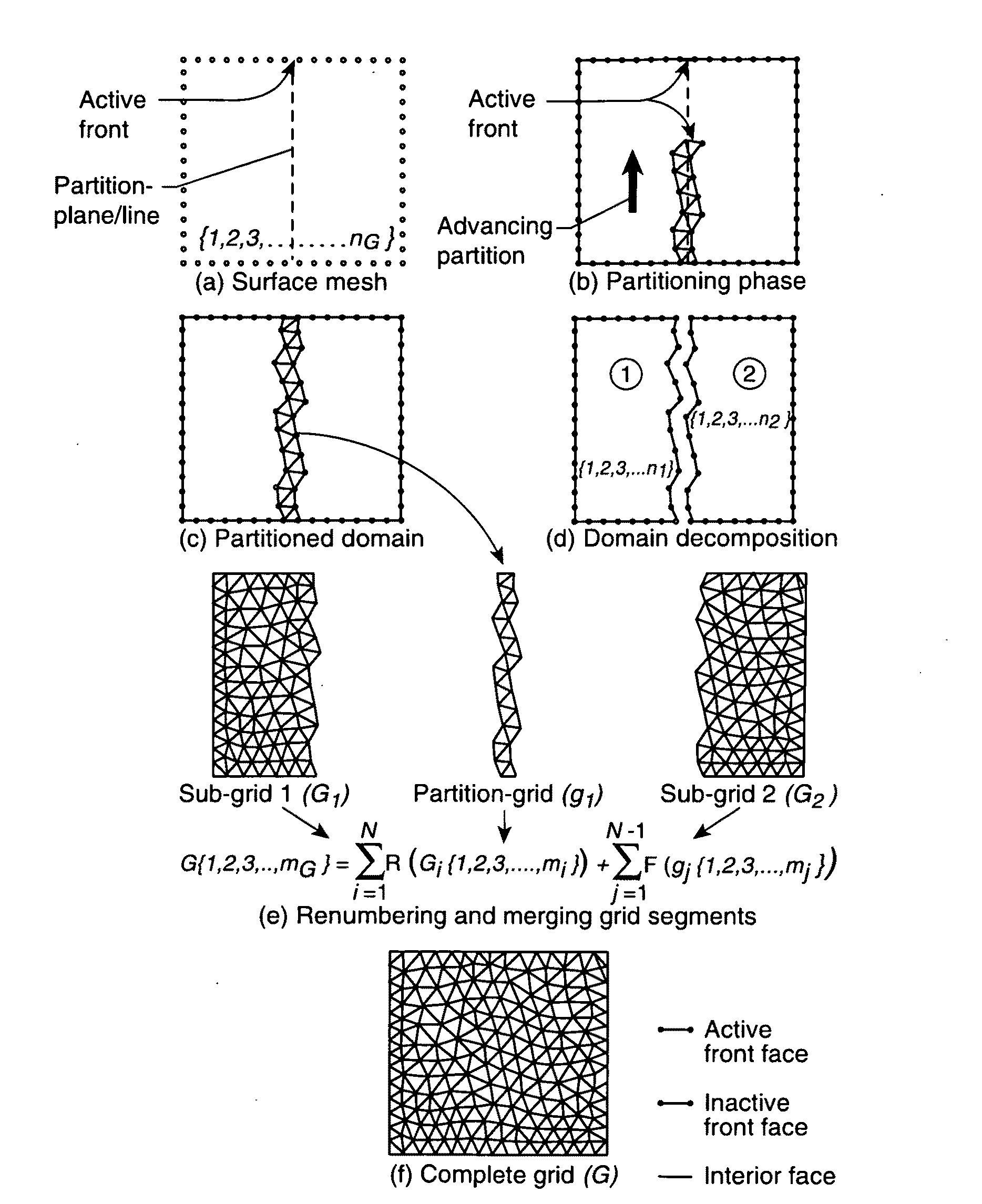
[0024]The present method and system of domain decomposition is an extension of the meshing methodology incorporated in the grid generation software VGRID and is preferably described by first presenting the underlying grid techniques followed by their implementation for domain decomposition. The following symbols are used herein in describing embodiments of the invention:[0025]A cell aspect ratio[0026]gj{1, 2, 3, . . . mj} jth partition-grid containing a set of mj field elements[0027]Gi{1, 2, 3, . . . mi} ith sub-grid containing a set of mi field elements in subdomain i[0028]G{1, 2, 3, . . . mG} global grid containing a set of mG field elements in the main domain[0029]k empirical parameter used for computing the center of mesh density[0030]L level of binary domain partitioning / decomposition[0031]mi mass of ith the particle; also number of grid elements[0032]N total number of subdomains / sub-grids[0033]nG number of surface mesh elements[0034]n number of particles; number of boundary gr...


PUM


Abstract

In a method for domain decomposition for generating unstructured grids, a surface mesh is generated for a spatial domain. A location of a partition plane dividing the domain into two sections is determined. Triangular faces on the surface mesh that intersect the partition plane are identified. A partition grid of tetrahedral cells, dividing the domain into two sub-domains, is generated using a marching process in which a front comprises only faces of new cells which intersect the partition plane. The partition grid is generated until no active faces remain on the front. Triangular faces on each side of the partition plane are collected into two separate subsets. Each subset of triangular faces is renumbered locally and a local / global mapping is created for each sub-domain. A volume grid is generated for each sub-domain. The partition grid and volume grids are then merged using the local-global mapping.

Description

CROSS-REFERENCE TO RELATED APPLICATION[0001]This application claims priority to and the benefit of U.S. Provisional Application 61 / 092,446 filed on Aug. 28, 2008, which is hereby incorporated by reference in its entirety.ORIGIN OF THE INVENTION[0002]The invention was made by an employee of the United States Government and may be manufactured and used by or for the Government of the United States of America for governmental purposes without the payment of any royalties thereon or therefor.FIELD OF THE INVENTION[0003]The present invention relates generally to computational fluid dynamics and, more particularly, relates to methods of domain decomposition for grid generation.BACKGROUND[0004]Thanks to recent advances in the field of Computational Fluid Dynamics (CFD), engineers and researchers are nowadays able to solve large-scale, real world aerodynamic problems that had not been tractable a few years ago. Among the enabling factors contributing to this success are: 1) advanced grid ge...

Claims


Application Information

Patent Timeline
Patent Type & Authority Applications(United States)
IPC IPC(8): G06T11/20
CPCG06T17/205G06T17/20
Inventor PIRZADEH, SHAHYAR Z.BANIHASHEMI, SOHEILA
Owner NASA
Why Eureka
Try Eureka