Apparatus for tracking an object using a moving camera and method thereof

a technology of moving camera and object, applied in the direction of instruments, television systems, signal generators with optical-mechanical scanning, etc., can solve the problems of inability to perform further tracking, inability to allow the object to be seen more accurately, and inconvenient calibration

Inactive Publication Date: 2010-06-03
ELECTRONICS & TELECOMM RES INST
View PDF8 Cites 17 Cited by
  • Summary
  • Abstract
  • Description
  • Claims
  • Application Information

AI Technical Summary

Benefits of technology

[0009]The present invention proposes to solve the above problem. It is an object of the present invention to provide an apparatus that dynamically extracts an object to be tracked from an image collected through a camera and then calculates the probability that it is the object to be tracked through a statistical method using the color distribution of the object to be tracked obtained from modeling the extracted object to be tracked and the color distribution of the background obtained by continuously performing modeling on the background, thereby making it possible to perform object tracking with high reliability even when using a moving camera, and a method thereof.
[0013]Furthermore, the apparatus for tracking the object further includes a post-processing unit that removes noise from the resultant image of the data processing unit to highlight the object to be tracked.
[0029]According to the present invention, the following acting effects can be obtained:
[0030]The method for tracking the object using the moving camera according to the present invention, which is a method of capable of effectively tracking an object to be tracked by controlling the division direction of the camera according to the motion of the object to be tracked, makes a tough object tracking possible even in an environment where the object and background move together compared to a method for tracking an object using a still camera in the related art. This is the reason that modeling is performed on only the object to be tracked in the related art. However, modeling is performed for each frame by also considering the neighboring environment thereof in the present invention.
[0032]Moreover, the tracking based on the probability using the color distribution of the object to be tracked rather than the template matching method is performed, making it possible to continuously track the object to be tracked, even though the size thereof is changed.

Problems solved by technology

However, in the case of the method for tracking the moving object using a still camera, it has a disadvantage in that further tracking cannot be performed, if the moving object gets out of the range of a screen, and a digital zoom rather than an optical zoom should be used in order to see the object more accurately.
However, this does not allow the object to be seen more accurately but merely allows only the information of the original image to be more largely magnified so as to be seen.
In the case of the method for tranking the moving object using two cameras, a calibration step of two cameras is required and a gap occurs in the movable range of the PTZ when they are used over a long time, causing an inconvenience that the calibration should be performed again.
However, in the cases of the MeanShift and the CamShift, an original Shift method has been proposed for a camera that has little motion so that if the camera is continuously moved, having a disadvantage that tracking reliability is rapidly dropped.
In the case of the ABCShift, although modeling on the background is continuously performed while tracking the object, the modeling of the object to be actually tracked uses a sheet of an initial frame and assumes the entirety of an area input from a user as the object to be tracked, having a limitation in more accurately modeling the object.

Method used


Image

  • Apparatus for tracking an object using a moving camera and method thereof
  • Apparatus for tracking an object using a moving camera and method thereof
  • Apparatus for tracking an object using a moving camera and method thereof

Examples


Embodiment Construction

[0038]Hereinafter, the preferred embodiments of the present invention will be described in detail with reference to the accompanying drawings. Herein, the repeated explanation and the detailed description on the well-known function and constitution which may make the gist of the present invention obscure will be omitted. The embodiments of the present invention will be provided in order to more perfectly explain the present invention to those skilled in the art. Therefore, the shape, size or the like of elements in the drawings may be exaggerated for more definite explanation. Like reference numerals refer to like elements throughout.

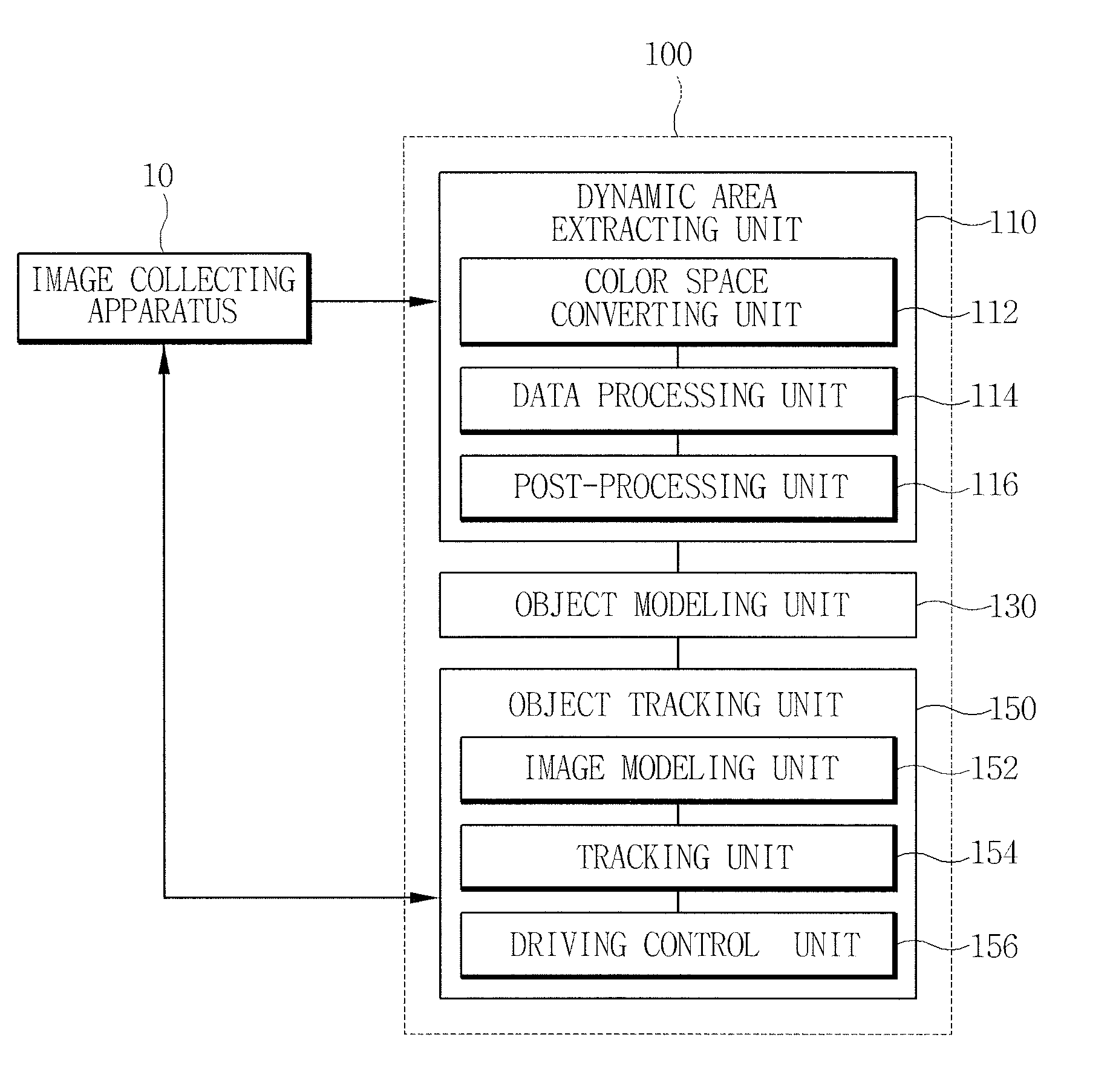
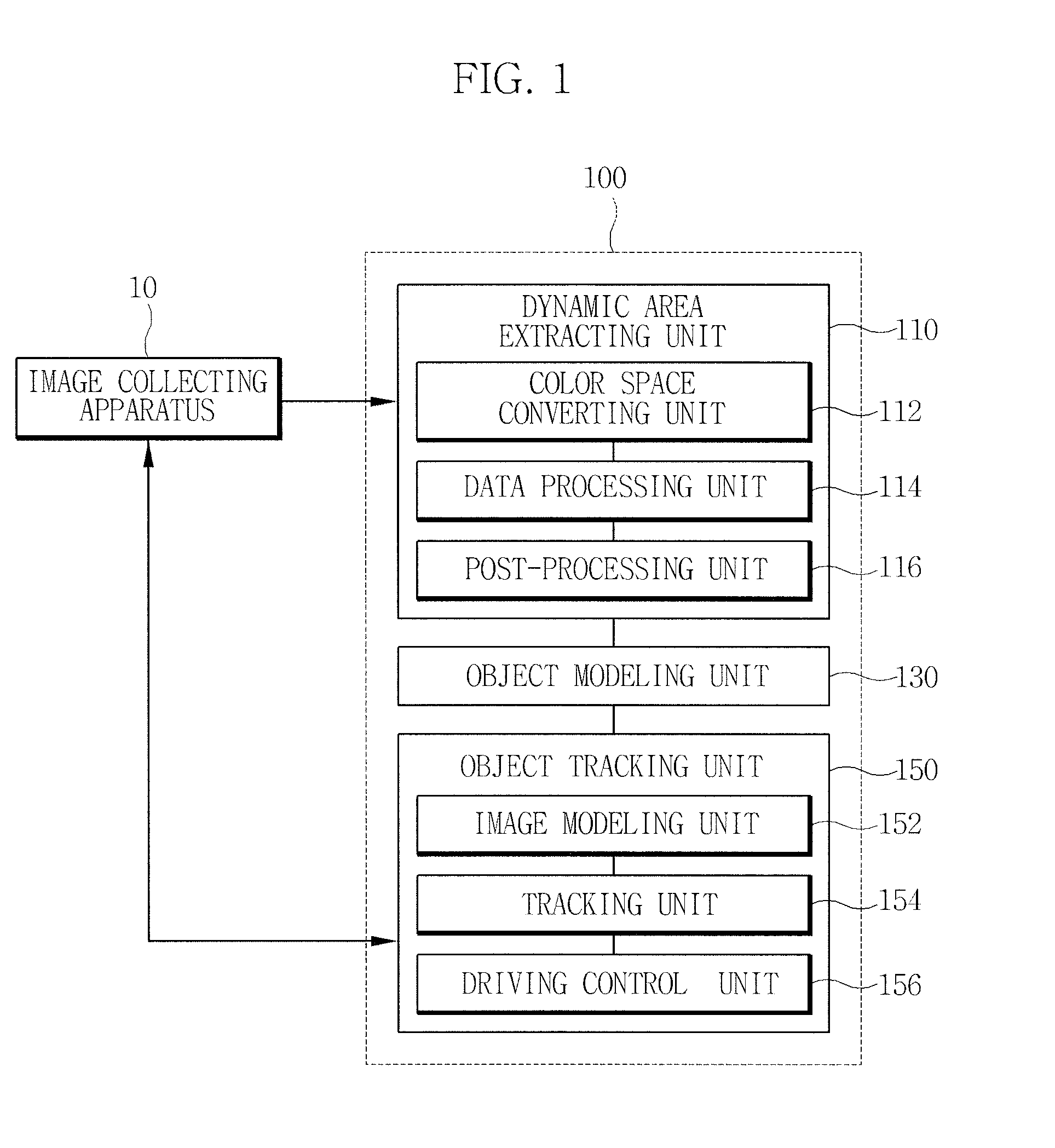
[0039]FIG. 1 is a diagram explaining an apparatus for tracking an object using a moving camera according to an embodiment of the present invention.

[0040]Referring to FIG. 1, the object tracking apparatus 100 according to the present invention includes a dynamic area extracting unit 110 that extracts an object to be tracked from an image frame collected ...


PUM


Abstract

Provided is an apparatus for tracking an object, including: a dynamic area extracting unit that extracts an object to be tracked from an image frame collected through an image collecting apparatus; an object modeling unit that models the object to be tracked extracted through the dynamic area extracting unit to calculate the color distribution of the object to be tracked; and an object tracking unit that calculates the color distribution of a next image frame collected through the image collecting apparatus, after calculating the color distribution of the object to be tracked, and calculates a posterior probability that each pixel belongs to the object to be tracked in the next image frame based on the calculated color distribution of the next image frame and the color distribution of the object to be tracked to track the object to be tracked.

Description

RELATED APPLICATIONS[0001]The present application claims priority to Korean Patent Application Serial Number 10-2008-0121648, filed on Dec. 3, 2008 and Korean Patent Application Serial Number 10-2009-100761, filed on Oct. 22, 2009, the entirety of which are hereby incorporated by reference.BACKGROUND OF THE INVENTION[0002]1. Field of the Invention[0003]The present invention relates to an apparatus for tracking an object using a moving camera and a method thereof, and more particularly, to an apparatus that dynamically models an object to be tracked for a short time and tracks the object by continusouly moving a camera in order to track the modeled object, and a method thereof.[0004]2. Description of the Related Art[0005]A general method for tracking a moving object mostly uses a still camera or two cameras, wherein one is used as reference and the other is used as pan / tilt / zoom (PTZ).[0006]However, in the case of the method for tracking the moving object using a still camera, it has...

Claims


Application Information

Patent Timeline
Patent Type & Authority Applications(United States)
IPC IPC(8): G06K9/00H04N11/00G06V10/24
CPCG06T7/20G06K9/32G06V10/24
Inventor WON, JONGHOKOH, EUNJINBAE, CHANGSEOKKIM, JINTAE
Owner ELECTRONICS & TELECOMM RES INST
Why Eureka
Try Eureka