Hybrid Vehicle Propulsion Energy Storage System

a technology of energy storage system and hybrid vehicle, which is applied in the direction of propulsion by batteries/cells, capacitors, battery/fuel cell control arrangement, etc., can solve the problems of limited battery life, high cost one or more replacement of battery packs, and battery power limitation

Inactive Publication Date: 2010-06-03
SHEPPARD MULLIN RICHTER & HAMPTON
View PDF10 Cites 59 Cited by
  • Summary
  • Abstract
  • Description
  • Claims
  • Application Information

AI Technical Summary

Benefits of technology

[0010]An aspect of the invention involves an energy storage cell pack cradle assembly of an energy storage cell pack including multiple rows of energy storage cells oriented along a dominant axis of vibration, the energy storage cells including an energy storage cell body with a casing, opposite end portions, and respective electrically conductive terminals extending from the end portions. The energy storage cell pack cradle assembly includes a first cradle member including a plurality of energy storage cell body supporting structures including respective holes, a second cradle member includi

Problems solved by technology

However, the chemical reaction that occurs internal to a battery during charging and discharging typically limits deep-cycle battery life to hundreds of charge/discharge cycles.
This characteristic means that the battery pack has to be replaced at a high cost one or more times during the life of a hybrid-electric or all-electric vehicle.
Batteries are somewhat power-limited because the chemical reaction therein limits the rate at which batteries can accept energy during charging and supply energy during discharging.
In a hybrid-electric vehicle application, the battery power limitation manifests itself as an internal series resistance tha

Method used


Image

  • Hybrid Vehicle Propulsion Energy Storage System
  • Hybrid Vehicle Propulsion Energy Storage System
  • Hybrid Vehicle Propulsion Energy Storage System

Examples


Embodiment Construction

[0034]This disclosure of the invention is submitted in furtherance of the constitutional purposes of the U.S. patent Laws “to promote the progress of science and useful arts” (Article 1, Section 8).

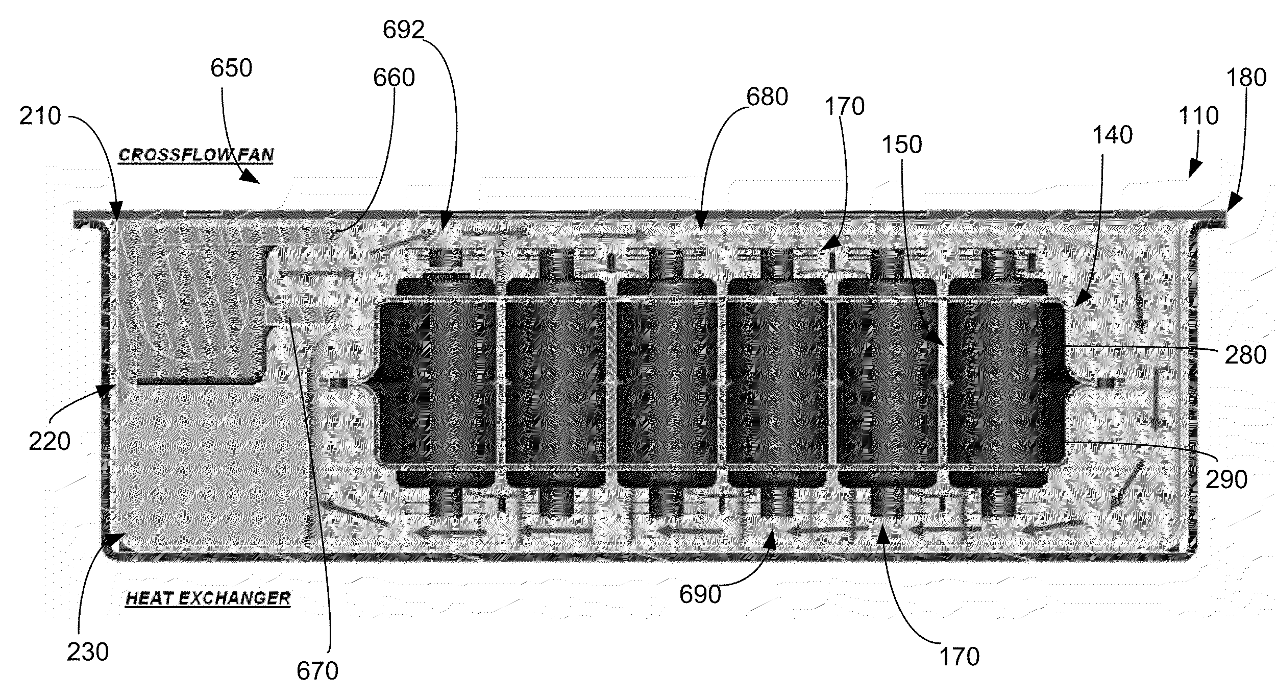
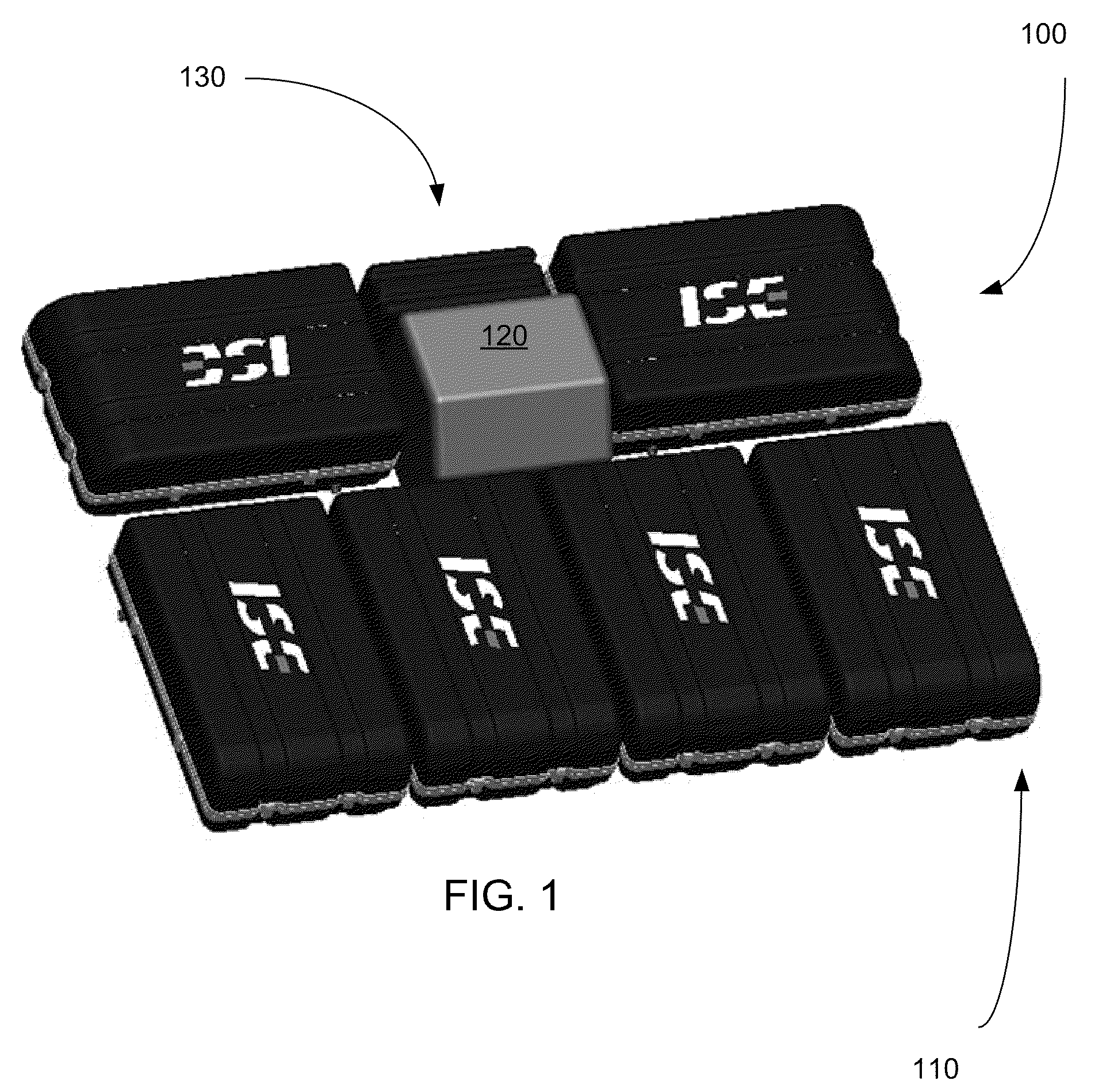
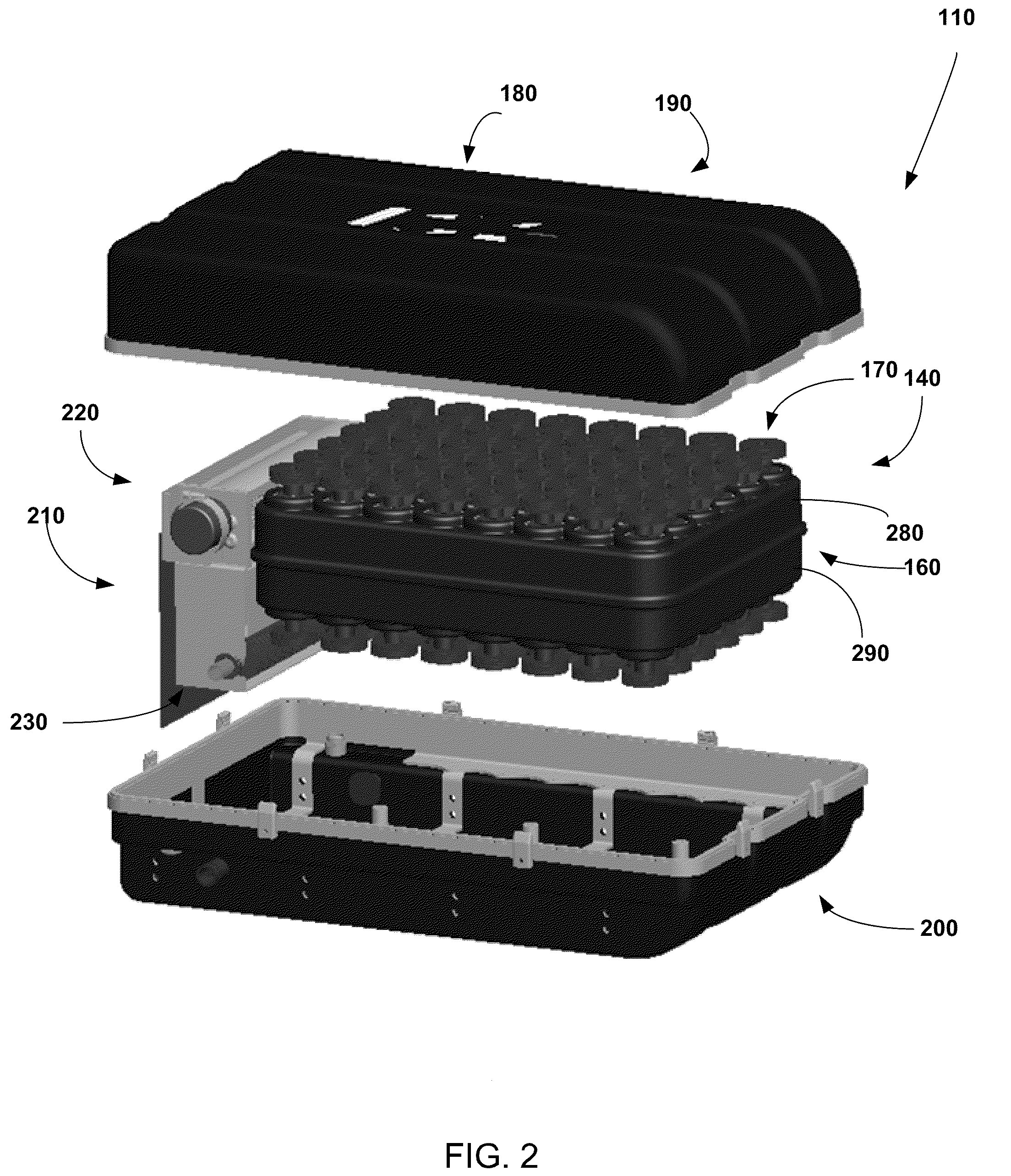
[0035]With reference to FIG. 1, an ultracapacitor energy storage system 100 constructed in accordance with an embodiment of the invention will be described. The ultracapacitor energy storage system 100 includes a plurality of ultracapacitor energy storage cell packs 110 connected to a central water chiller 120 or cooling supply for cooling ultracapacitors of the ultracapacitor energy storage cell packs 110, and a controller 130 for controlling cooling of the ultracapacitor energy storage cell packs 110 and / or controlling electrical functions (and / or other functions) of the ultracapacitor energy storage cell packs 110. As illustrated in this particular embodiment, each ultracapacitor energy storage cell pack 110 here includes 48 (6×8) ultracapacitors oriented so that the longitudinal axis ...


PUM

PropertyMeasurementUnit
Poweraaaaaaaaaa
Currentaaaaaaaaaa
Currentaaaaaaaaaa

Abstract

An energy storage cell pack cradle assembly for holding multiple rows of energy storage cells oriented along a dominant axis of vibration includes a first cradle member including a plurality of energy storage cell body supporting structures including respective holes; a second cradle member including a plurality of energy storage cell body supporting structures including respective holes; and one or more fasteners connecting the first cradle member and the second cradle member together. The energy storage cell body supporting structures are configured to structurally support the energy storage cells, with the energy storage cells oriented along a dominant axis of vibration, by energy storage cell bodies of the energy storage cells with respective electrically conductive terminals extending through the respective holes without structural support of the electrically conductive terminals by the cradle members.

Description

RELATED APPLICATIONS[0001]This is a continuation of pending application Ser. No. 12 / 343,957 filed Dec. 24, 2008, which is a continuation of pending application Ser. No. 12 / 343,271 filed Dec. 23, 2008. All of these applications are incorporated by reference herein as though set forth in full.FIELD OF THE INVENTION[0002]The field of the invention generally relates to an energy storage specially adapted for a hybrid electric vehicle. In particular, the invention relates to a high-voltage, high-power ultracapacitor energy storage pack composed of a large number of serially connected individual low-voltage ultracapacitor cells that store propulsion energy.BACKGROUND OF THE INVENTION[0003]The connecting together of individual battery cells for high-voltage, high-energy applications is well known. However, the chemical reaction that occurs internal to a battery during charging and discharging typically limits deep-cycle battery life to hundreds of charge / discharge cycles. This characterist...

Claims


Application Information

Patent Timeline
IPC IPC(8): H02H9/04H05K7/20
CPCH01G2/08Y10T29/49002H01M10/5004H01M10/5016H01M10/503H01M10/5051H01M10/5057H01M10/5077H01M10/5095H05K7/20863Y02E60/13Y02T10/7022H01G11/10H01G11/82H01G9/155H01M10/625H01M10/6553H01M10/663H01M10/6556H01M10/6568H01M10/643H01M10/613B60L2240/547B60L2270/145B60L50/40B60L50/64B60L58/15Y02T10/70Y02E60/10H01G11/14
Inventor NGUYEN, VINH-DUYSMITH, ALEXANDER J.STONE, KEVIN T.MEDINA, ALFONSO O.
Owner SHEPPARD MULLIN RICHTER & HAMPTON
Why Eureka
Try Eureka