Portable heat dissipation device with cross flow fan

a heat dissipation device and cross-flow fan technology, which is applied in the direction of cooling/ventilation/heating modification, instruments, computing, etc., can solve the problems of poor heat dissipation of electronic devices, difficult for electronic devices to run for a very long time, and failure of electronic devices to properly function, etc., to achieve extended time interval of operation, high heat dissipation performance, and extended lifespan

Inactive Publication Date: 2010-06-03
CHANG SU BEN +2
View PDF10 Cites 20 Cited by
  • Summary
  • Abstract
  • Description
  • Claims
  • Application Information

AI Technical Summary

Benefits of technology

[0006]An objective of the present invention is to provide a portable heat dissipation device fe...

Problems solved by technology

However, the overall configuration is set in a trend of being light-weighted and compact and this often leads to poor heat dissipation of the electronic device, making it difficult for the electronic device to run for a very long while.
In addition, it is very likely that dust covers on an existing heat dissipation device built in the electronic device, which may deteriorate the dissipation of heat, eventually making the electronic device failing to properly function.
However, increasing the fan size means a corresponding increas...

Method used


Image

  • Portable heat dissipation device with cross flow fan
  • Portable heat dissipation device with cross flow fan
  • Portable heat dissipation device with cross flow fan

Examples


first embodiment

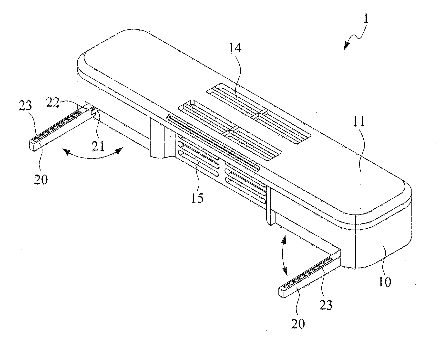
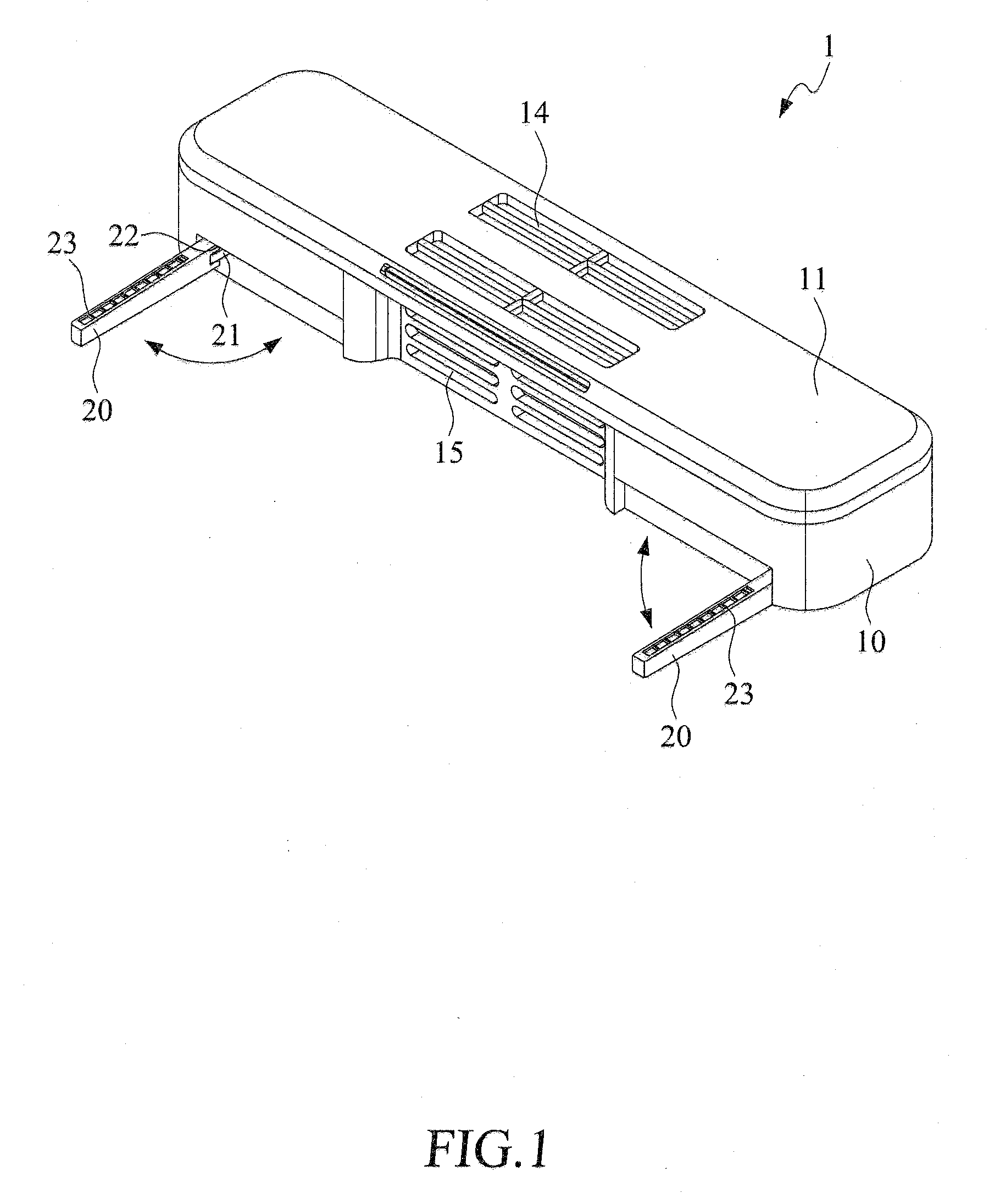
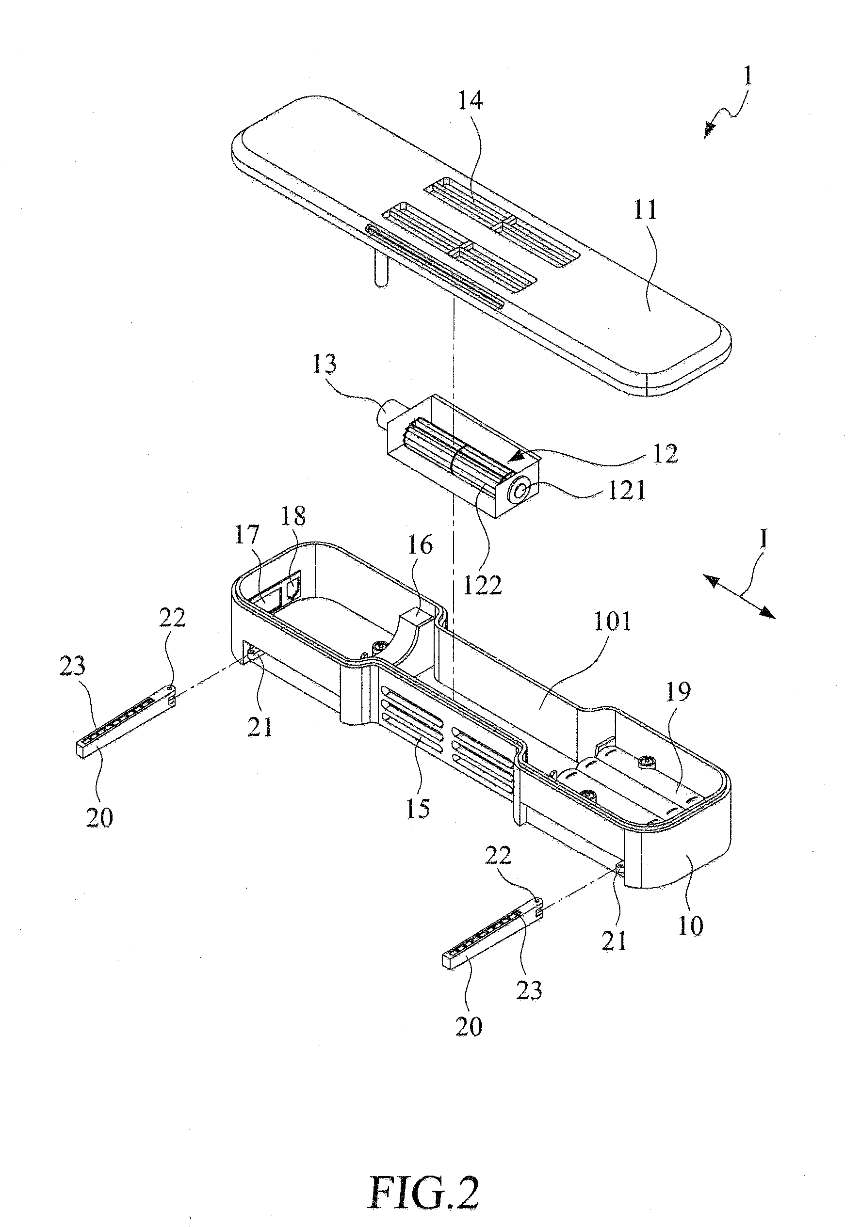
[0031]With reference to the drawings and in particular to FIGS. 1 and 2, a portable heat dissipation device constructed in accordance with the present invention comprises an enclosure 1 that is configured for easy carrying and use. The enclosure 1 is comprised of a lower container 10 and a top cover 11. The enclosure 1 forms therein a receiving space 101 that is comprised of a plurality of chambers for respectively receiving and retaining inside parts / components / devices of the portable heat dissipation device, which include an air flow generation device that is set in a particular chamber. The air flow generation device comprises a cross flow fan 12 and a driving source 13. As shown, the cross flow fan 12 is set in a middle chamber of the lower container 10. The driving source 13 is coupled to a left-side end of the cross flow fan 12 and is positioned leftward of the cross flow fan 12 and fit in a complementary shaped recess defined in an internal wall of the lower container 10 for ...

second embodiment

[0040]With reference to the drawings and in particular to FIGS. 5 and 9, a portable heat dissipation device constructed in accordance with the present invention is shown. In this embodiment, the enclosure defines at least one first air flowing opening 14a and at least one second air flowing opening 15a. A concave accommodating dock 102 is formed in the receiving space 101 of the enclosure 1. The concave accommodating dock 102 is provided with a first section 102a and a second section 102b correspondingly opposite to the first section 102a.

[0041]A pair of first conductive elements 103a, 103b are spaced each other and arranged at the first section 102a. A pair of second conductive elements 104a, 104b are spaced each other and arranged at the second section 102b.

[0042]A direction-exchangeable air flow generation module 3 comprising an assembly frame 31 having a first end plate 32 and a second end plate 33 correspondingly opposite to the first end plate 31. A pair of conductive termin...


PUM


Abstract

A portable heat dissipation device is provided for operation with various devices of different purposes for heat dissipation therefrom and includes an enclosure and an air flow generation device. The air flow generation device is set in a given chamber inside the enclosure to effect flowing of air, causing air to enter through an inlet opening defined in a top of the enclosure and forcing the air flowing out through an outlet opening defined in a front wall of the enclosure. The portable heat dissipation device, when applied to remove heat, provides high performance of heat dissipation and effectively extended time interval of operation to thereby extend the lifespan of the device.

Description

CROSS-REFERENCES TO RELATED APPLICATIONS[0001]This application is a continuation-in-part of Ser. No. 12 / 289,103 filed on Oct. 21, 2008, entitled “Portable Heat Dissipation Device with Cross Flow Fan”, currently pending.FIELD OF THE INVENTION[0002]The present invention relates to a portable heat dissipation device, and in particular to a heat dissipation device that supports heat dissipation operations for various devices of different purposes, whereby the use of the portable heat dissipation device ensures high performance of heat removal and effectively extended time interval of operation and extended lifespan.BACKGROUND OF THE INVENTION[0003]With the increasing development of technology and science, the performance of electronic devices has greatly improved, such as the remarkable increase of the operation speed of a central processing unit (CPU) or the development of multiple CPU based operation configuration. Consequently, the amount of data processed and the speed of processing...

Claims


Application Information

Patent Timeline
IPC IPC(8): H05K7/20
CPCG06F1/203G06F1/1632
Inventor CHANG, SU-BENCHANG, WEI-FUCHANG, WEI-YU
Owner CHANG SU BEN
Why Eureka
Try Eureka