Eureka AIR delivers breakthrough ideas for toughest innovation challenges, trusted by R&D personnel around the world.

Ceiling recessed-type lamp unit

Inactive Publication Date: 2010-06-03
TESCO ECO LIGHTING
View PDF1 Cites 5 Cited by
  • Summary
  • Abstract
  • Description
  • Claims
  • Application Information

AI Technical Summary

Benefits of technology

[0014]In view of the above circumstances, it is an object of the present invention to provide a ceiling recessed-type lamp unit capable of facilitating recessedly mounting a unit body to a ceiling, while ensuring the reliability of mounting the unit body to the ceiling, regardless of a lamp unit's size.
[0016]The ceiling recessed-type lamp unit of the present invention has the above feature. Thus, in an operation of recessedly mounting the unit body to the ceiling, the engagement member is preliminarily set in the non-engagement position, and the unit body is inserted into the opening of the ceiling. Then, the engagement member is set in the engagement position simply by rotating the engagement member in the second direction. This makes it possible to facilitate recessedly mounting the unit body to the ceiling, regardless of a lamp unit's size. Furthermore, the engagement member in the engagement position is continuously applied with the downward biasing force from the elastic member. Thus, the engagement position can be stably maintained to allow the unit body to be reliably mounted to the ceiling, while preventing the unit body from wobbling, or drooping / falling down from the ceiling.
[0018]Preferably, the ceiling recessed-type lamp unit of the present invention further includes shock attenuation means for attenuating shock occurring when the engagement member is brought into engagement with the back surface of the ceiling after being moved downwardly by the downward biasing force of the elastic member. In the ceiling recessed-type lamp unit provided with the shock attenuation means, when the engagement member is brought into engagement with the back surface of the ceiling after being moved downwardly by the downward biasing force of the elastic member, resulting shock can be attenuated to prevent damage to the ceiling. In the ceiling recessed-type lamp unit devoid of the shock attenuation means, there exists a need for setting the downward biasing force of the elastic member in a limited range in order to prevent damage to the ceiling, in some cases. In contrast, the ceiling recessed-type lamp unit provided with the shock attenuation means can employ an elastic member having a relatively strong downward biasing force, to allow the unit body to be more reliably mounted to the ceiling, while reliably preventing the unit body from wobbling, or drooping / falling down from the ceiling.
[0020]In ceiling recessed-type lamp unit of the present invention, the engagement member is moved from the non-engagement position to the engagement position by manually rotating the first engagement portion of the engagement portion, as mentioned above. Preferably, the operation of manually rotating the engagement portion is performed using a manual tool adapted to be inserted from an opening (or hole, gap, etc.) in a bottom of the unit body. In view of facilitating the operation of rotating the first engagement portion using the manual tool, the elastic member applying the downward biasing force to the engagement member is preferably disposed above the first engagement portion of the engagement member. Specifically, when the elastic member is disposed above the first engagement portion of the engagement member, the first engagement portion of the engagement member can be disposed on a downward side accordingly, to facilitate the operation of rotating the first engagement portion using the manual tool which is to be inserted from the opening in the bottom of the unit body. This makes it possible to provide more enhanced efficiency in the operation of recessedly mounting the unit body to the ceiling. According to need, the engagement member in the engagement position can be moved upwardly and then rotated to return to the non-engagement position. Preferably, this operation is also performed using a manual tool adapted to be inserted from an opening (or hole, gap, etc.) in the bottom of the unit body.
[0021]Preferably, in the ceiling recessed-type lamp unit of the present invention, the unit body has a lateral plate formed with a slide slot extending vertically, and the support member is engaged with the slide slot vertically slidably in such a manner as to adjustably change a vertical fixing position of the support member relative to the unit body in a continuous manner. According to this feature, in an operation of changing the vertical fixing position of the support member depending on a thickness of a ceiling board in a mounting site, a need for taking out a fixation screw can be eliminated to provide more enhanced efficiency of the mounting operation.
[0022]As above, the ceiling recessed-type lamp unit of the present invention can facilitate recessedly mounting a unit body to a ceiling in a reliable manner, regardless of a lamp unit's size.

Problems solved by technology

The leaf spring-based mounting structure has a problem that, if the elastic restoring force of the leaf spring deteriorates due to fatigue of the leaf spring or the like, the lamp unit is likely to wobble, or droop or fall down from the ceiling, only by a slight external force applied thereto.
Although the mounting structure disclosed in the patent Publication 1 is designed to adjustably change a fixing position of the leaf spring so as to allow the elastic restoring force to be adequately set depending on mounting environments, it is unable to radically solve the above problem, as long as it is the leaf spring-based mounting structure.
Moreover, in the leaf spring-based mounting structure, during an operation of demounting the unit body from the ceiling, the ceiling is likely to be damaged, because the unit body has to be forcibly pulled out of the ceiling downwardly under a condition that the elastic restoring force of the leaf spring is applied to the ceiling.
As above, the mounting structure disclosed in the patent Publication 2 involves an extremely complicated operation to mounting / demounting the unit body to / from the ceiling.
Thus, an operator is required to take a lot of time and effort for the operation.
Moreover, an engaged state of the engagement member after being moved outwardly to the protruding position during the unit-body mounting operation is likely to become loose due to vibrations or the like.
This causes the same problem about wobbling, or drooping / falling from the ceiling, as that in the leaf spring-based mounting structure.
The mounting structure disclosed in the patent Publication 3 involves structural complexity, and requires a large mounting space.
Thus, it is difficult to apply this mounting structure to a small lamp unit.
The mounting structure disclosed in patent Publication 4 has difficulty in ensuring strength of the clamping plate, because it is composed of a single piece of plate.
Thus, it is difficult to apply this mounting structure to a small lamp unit.

Method used


Image

  • Ceiling recessed-type lamp unit
  • Ceiling recessed-type lamp unit
  • Ceiling recessed-type lamp unit

Examples


first embodiment

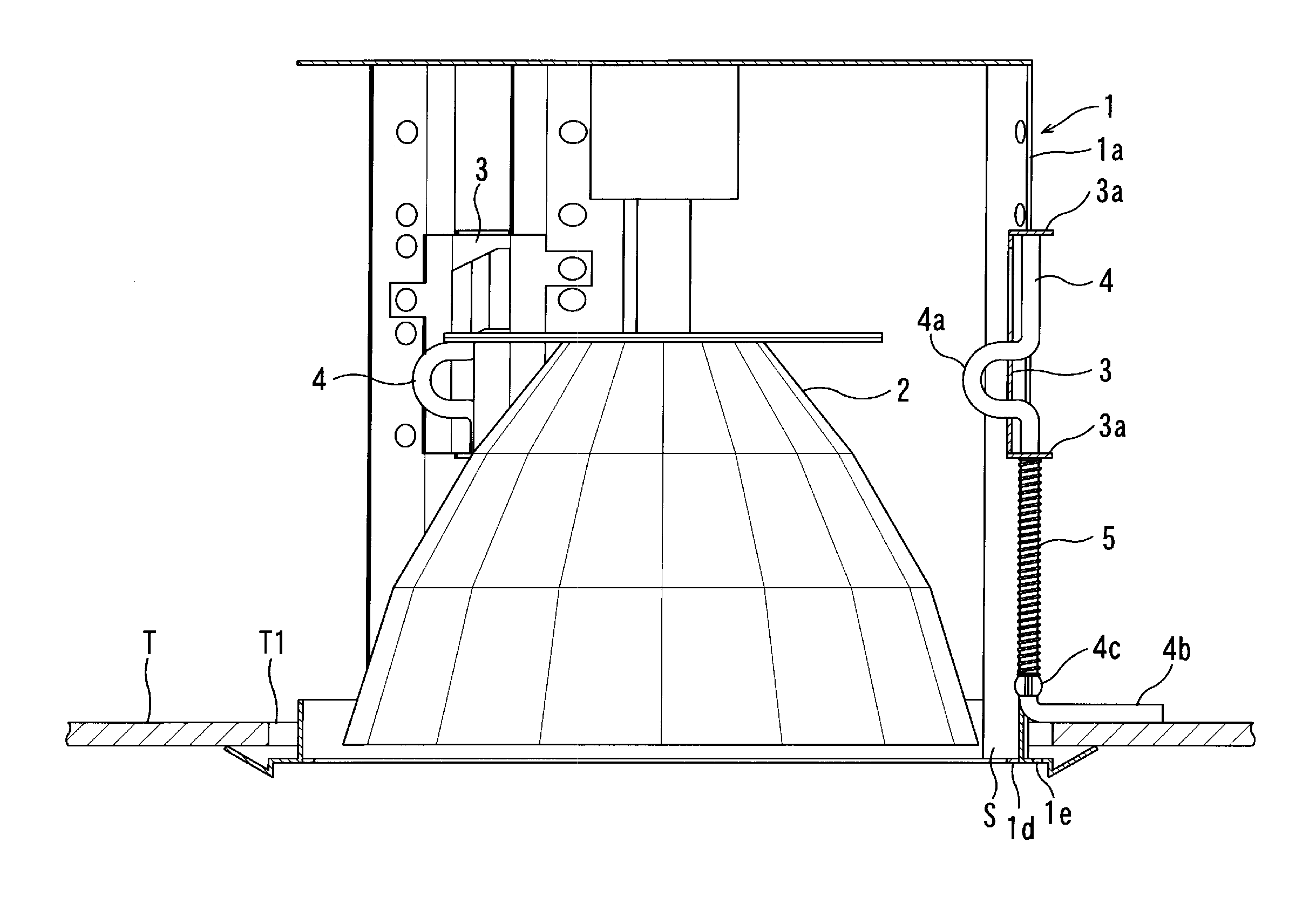
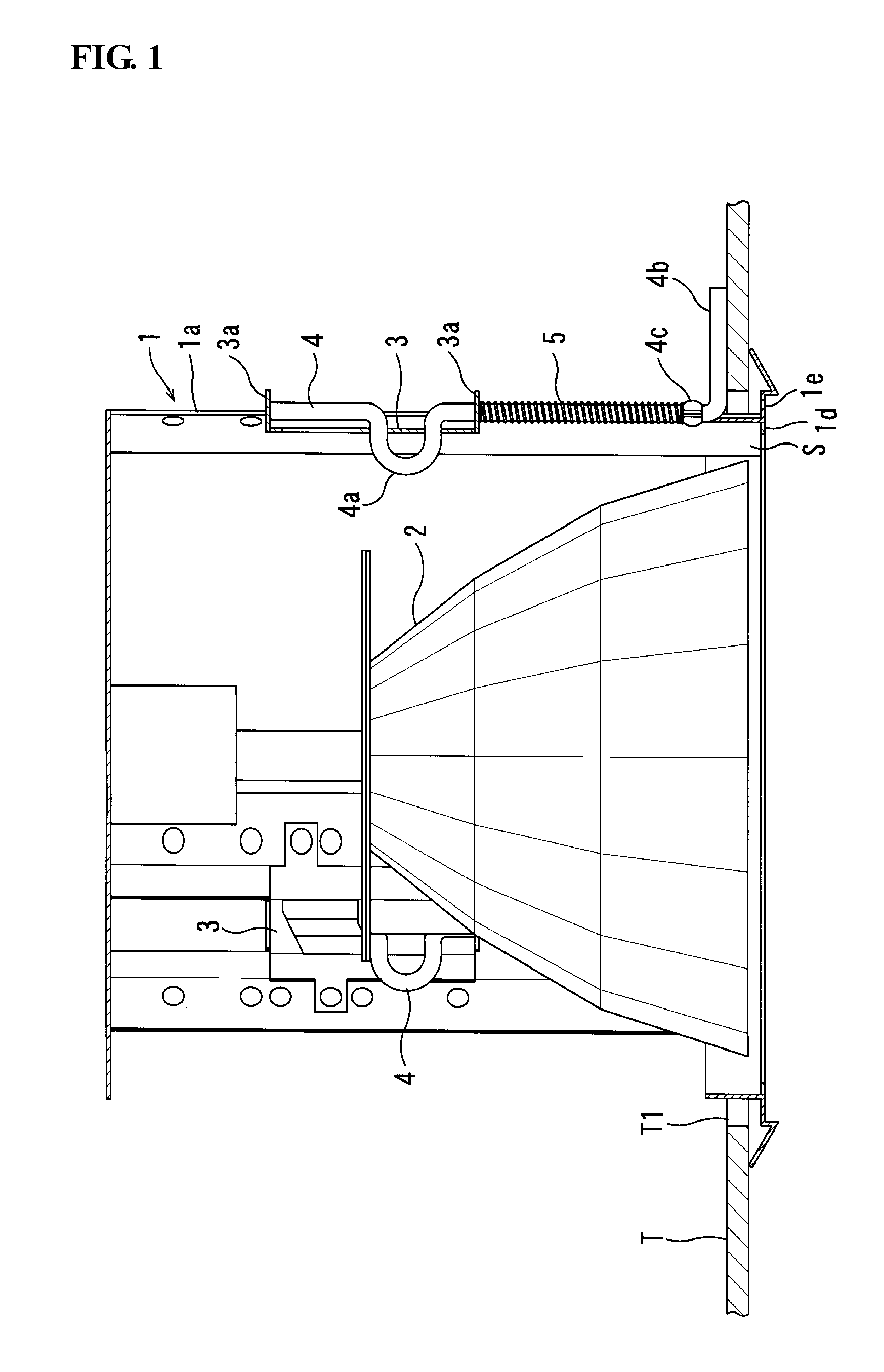
[0051]FIG. 1 is a sectional view showing a ceiling recessed-type lamp unit according to a first embodiment of the present invention, in a mounted state. As shown in FIG. 1, the ceiling recessed-type lamp unit according to the first embodiment comprises a unit body 1 adapted to be inserted from an opening T1 formed in a ceiling T, and recessedly mounted to the ceiling T (i.e., mounted to the ceiling T in a recessed manner or in a substantially flush-mounted manner). The unit body 1 internally has a hat-shaped reflector 2, and a lamp bulb (not shown) disposed inside the reflector 2.

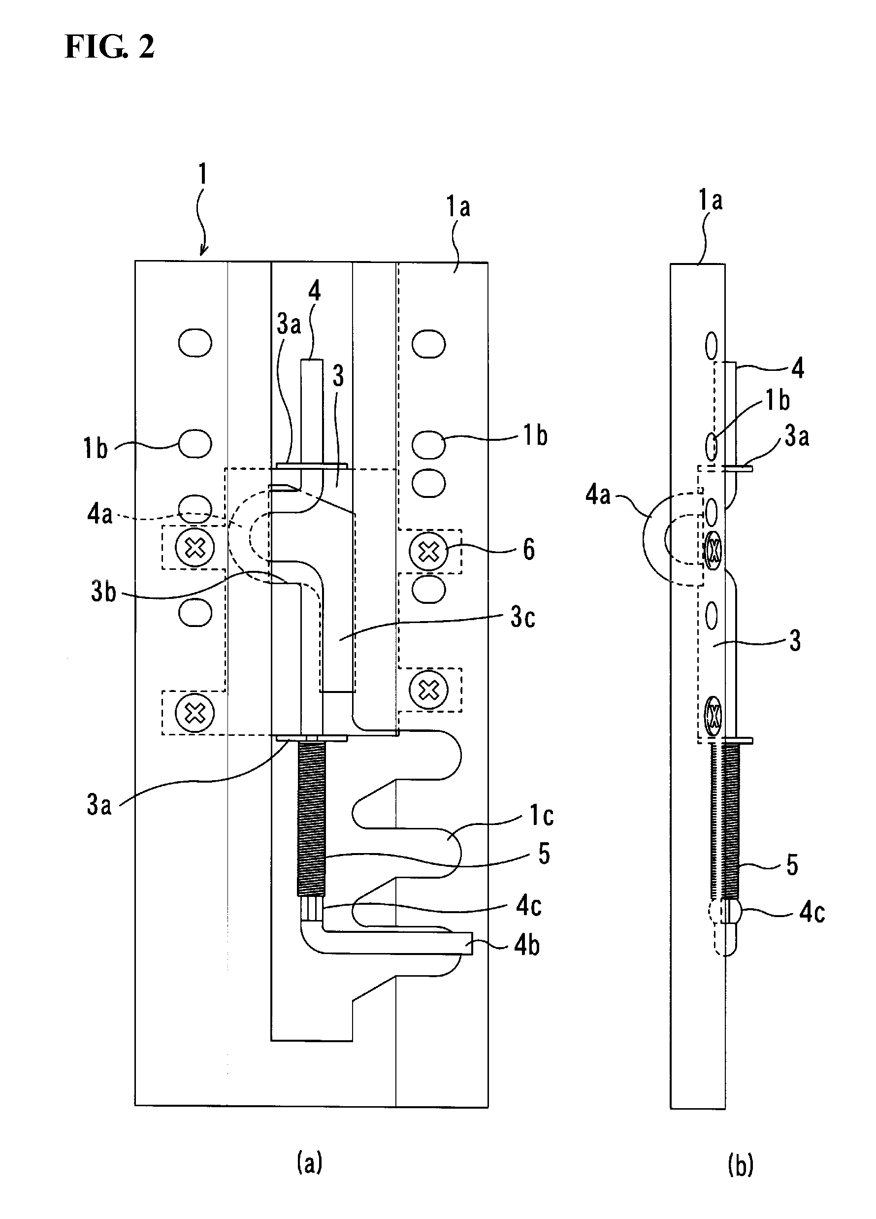
[0052]The lamp unit includes a support member 3 fixed to a lateral plate 1a of the unit body 1, and an engagement member 4 supported by upper and lower support portions 3a, 3a of the support member 3 in a vertically (i.e., upwardly and downwardly) movable manner and in a rotatable manner about a vertical (i.e., upward / downward) axis of the engagement member 4. The engagement member 4 is adapted to be engage...

second embodiment

[0063]FIG. 4 is a sectional view showing a ceiling recessed-type lamp unit according to a second embodiment of the present invention, in a mounted state. As with the first embodiment, the ceiling recessed-type lamp unit illustrated in FIG. 4 comprises a unit body 1 adapted to be inserted from an opening T1 formed in a ceiling T, and recessedly mounted to the ceiling T. The unit body 1 internally has a hat-shaped reflector 2, and a lamp bulb (not shown) disposed inside the reflector 2.

[0064]The lamp unit includes a support member 3 fixed to a lateral plate 1a of the unit body 1, and an engagement member 4 supported by upper and lower support portions 3a, 3a of the support member 3 in a vertically movable manner and in a rotatable manner about a vertical axis of the engagement member 4. The engagement member 4 is adapted to be engaged with a back surface of the ceiling T through a lower end (i.e., distal end) of an after-mentioned second engagement portion 4a thereof, so that the unit...


PUM


Abstract

Disclosed is a ceiling recessed-type lamp unit, which is capable of facilitating recessedly mounting a unit body to a ceiling, in a reliable manner regardless of a lamp unit's size. The lamp unit comprises a support member 3, and an engagement member 4. The support member 3 is formed with a latch portion adapted to engage the engagement member 4, and a guide groove successively extending from the latch portion downwardly. The engagement member 4 is formed with a first engagement portion 4a engageable with the latch portion, and a second engagement portion 4b engageable with a back surface of a ceiling T. The engagement member 4 is adapted to be rotated in a first direction about a vertical axis thereof, so that the first engagement portion 4a is latchedly engaged with the latch portion to allow the engagement member 4 to be set in a non-engagement position where the second engagement portion 4b avoids engagement with the back surface of the ceiling T. The engagement member is adapted, when it is in the non-engagement position, to be rotated in a second direction opposite to the first direction to release the engagement between the first engagement portion 4a and the latch portion, so that the engagement member 4 is moved downwardly along the guide slot by a biasing force of an elastic member, and set in an engagement position where the second engagement portion 4b is engaged with the back surface of the ceiling T.

Description

TECHNICAL FIELD[0001]The present invention relates to a ceiling recessed-type lamp unit, such as a downlight fixture, which is designed to be recessedly mounted in an opening formed in a ceiling.BACKGROUND ART[0002]A ceiling recessed-type lamp unit, such as a downlight fixture, is designed to be inserted from an opening formed in a ceiling from below the ceiling, and recessedly mounted to the ceiling (i.e., mounted to the ceiling in a recessed manner or in a substantially flush-mounted manner). Heretofore, there have been proposed various mounting structures for the recessed mounting.[0003]A typical one of the mounting structures is a type based on a leaf spring. For example, the following patent Publication 1 discloses a mounting structure comprising a generally V-shaped leaf spring which has an anchor arm fixed to a lateral surface of a unit body of a ceiling recessed-type lamp unit, and a free arm extending obliquely upwardly from a lower end of the anchor arm, wherein the unit b...

Claims


Application Information

Patent Timeline
IPC IPC(8): F21V15/00F21Y101/00
CPCF21V21/04F21V21/03F21V17/10
Inventor ISHIBASHI, MIYOJI
Owner TESCO ECO LIGHTING
Why Eureka
Eureka Blog
Learn More