
Active Vibration Control for Subterranean Drilling Operations

a technology of active vibration and drilling operations, applied in vibration drilling, directional drilling, borehole/well accessories, etc., can solve the problems of reducing the life of tools, and reducing the effectiveness of cutting action, so as to prevent or minimize the occurrence of harmful drill string/bha motion, improve one or more aspects of drilling process, and improve the effect of drilling process

Inactive Publication Date: 2010-06-10
BAKER HUGHES INC
View PDF47 Cites 76 Cited by
  • Summary
  • Abstract
  • Description
  • Claims
  • Application Information

AI Technical Summary

Benefits of technology

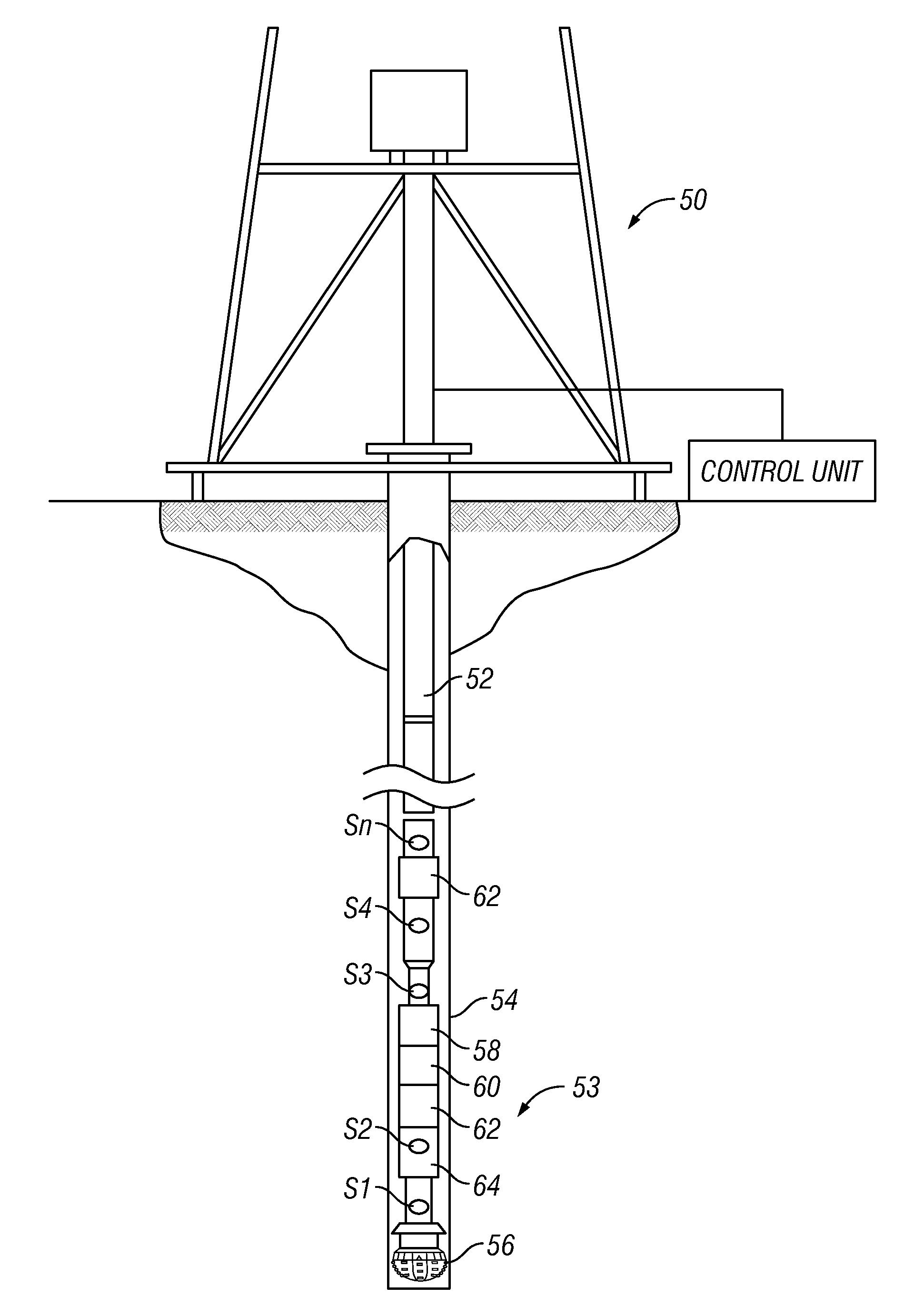
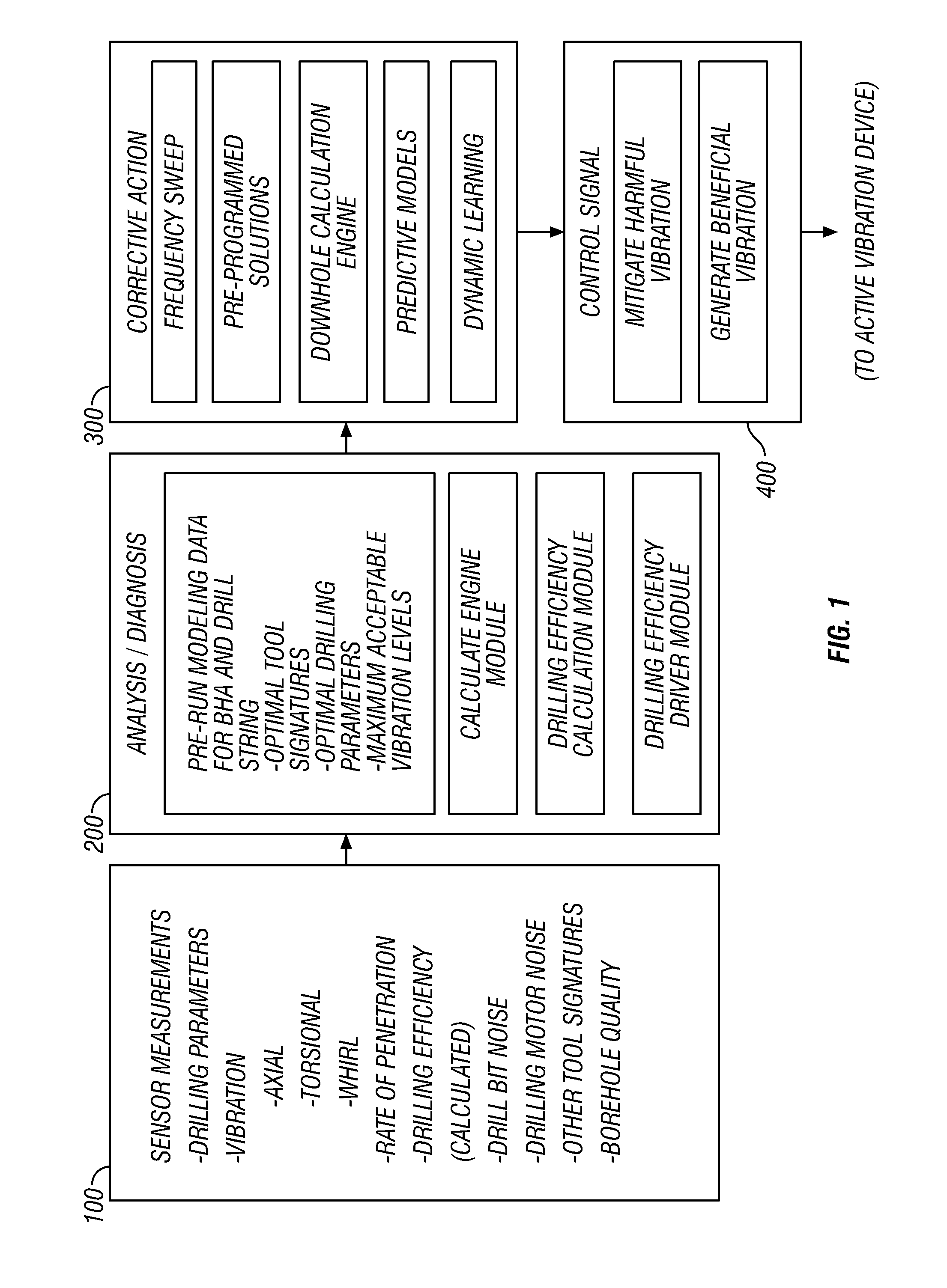
The present invention provides systems, methods, and devices for improving the drilling process by actively applying a dampening profile and / or controlled vibration to the drill string and / or bottomhole assembly. This can prevent or minimize the occurrence of harmful drill string motion or damage to the borehole, improve the quality of the drilling process, and increase the efficiency of the drilling process. The invention can use sensors to measure various parameters of interest and process the data to determine the nature and extent of non-beneficial conditions. The control unit can selectively apply a dampening profile and / or an active vibration control device to mitigate the non-beneficial conditions. The invention can be used with a conventional surface rig or downhole device and can be set to manage drilling performance or improve drilling efficiency. The active vibration control device can include biasing elements and a damping chamber to control axial vibrations and resulting accelerations in the drill string and / or bottomhole assembly.

Problems solved by technology

As can be appreciated, the cutting action of the drill bit against the earthen formation and the rotation of the drill string within the wellbore can produce a number of vibrations and motion that can cause a number of non-beneficial conditions such as a reduction in the effectiveness of the cutting action, damage to tooling, reduction in tool life, impairment of the effectiveness of downhole tools, etc.
One drawback to such conventional systems is that they cannot in a real time or near real time basis adapt to the dynamic drilling environment.
Such a shock absorber may have diminished value if the damaging vibrations are outside the range of the pre-set frequency and amplitude.
It will be appreciated, however, that such alterations may result in drilling at non-optimal conditions, e.g., reduced rate of penetration.

Method used


Image

  • Active Vibration Control for Subterranean Drilling Operations
  • Active Vibration Control for Subterranean Drilling Operations
  • Active Vibration Control for Subterranean Drilling Operations

Examples


Embodiment Construction

[0042]The teachings of the present invention can be applied in a number of arrangements to generally improve the drilling process by actively applying a dampening profile and / or a controlled vibration to a drill string and / or bottomhole assembly (BHA). Such improvements may include improvement in ROP, extended drill string life, improved bit and cutter life, reduction in wear and tear on BHA, and an improvement in bore hole quality. The term vibration as used herein refers generally to motion of a body but is not meant to imply an particular type of motion or time duration for the motion. The present invention is susceptible to embodiments of different forms. There are shown in the drawings, and herein will be described in detail, specific embodiments of the present invention with the understanding that the present disclosure is to be considered an exemplification of the principles of the invention, and is not intended to limit the invention to that illustrated and described herein....


PUM


Abstract

An active vibration control device improves drilling by actively applying a dampening profile and / or a controlled vibration to a drill string and / or bottomhole assembly (BHA). Embodiments of the present invention control the behavior of a drill string and / or BHA in order to prevent or minimize the occurrence of harmful drill string / BHA motion and / or to apply a vibration to the drill string / BHA that improves one or more aspects of the drilling process. Measurements of one or more selected parameters of interest are processed to determine whether the undesirable vibration or motion is present in the drill string or BHA and / or whether the drill string and / or BHA operation can be improved by the application of a controlled vibration. If either or both conditions are detected, corrective action is formulated and appropriate control signals are transmitted to one or more devices in the drill string and / or BHA.

Description

CROSS-REFERENCE TO RELATED APPLICATIONS[0001]This application is a divisional of U.S. Utility application Ser. No. 11 / 471,231, filed Jun. 20, 2006.BACKGROUND OF THE INVENTION[0002]1. Field of the Invention[0003]In one aspect, this invention relates generally to systems and methods for controlling the behavior or motion of a drill string and / or bottomhole assembly to optimize drilling operations.[0004]2. Description of Related Art[0005]To obtain hydrocarbons such as oil and gas, boreholes are drilled by rotating a drill bit attached at a drill string end. Conventionally, the drill bit is rotated by rotating the drill string using a rotary table at the surface and / or by using a drilling motor in a bottomhole assembly (BHA). As can be appreciated, the cutting action of the drill bit against the earthen formation and the rotation of the drill string within the wellbore can produce a number of vibrations and motion that can cause a number of non-beneficial conditions such as a reduction ...

Claims


Application Information

Patent Timeline
Patent Type & Authority Applications(United States)
IPC IPC(8): E21B7/24
CPCE21B44/00E21B28/00
Inventor WATKINS, LARRYFINCHER, ROGER W.ARONSTAM, PETER
Owner BAKER HUGHES INC
Learn More