
Closed transition automatic transfer switch assembly and associated method

Inactive Publication Date: 2010-06-10
EATON CORP
View PDF7 Cites 25 Cited by
  • Summary
  • Abstract
  • Description
  • Claims
  • Application Information

AI Technical Summary

Benefits of technology

[0013]In an alternate procedure, the bypass switch assembly may be used to provide the system with energy from the second power source. That is, instead of moving the first switch assembly into the second configuration and utilizing the first switch assembly to power the system load, after the first switch assembly is disengaged from the first energy source, the first switch assembly is left in the neutral configuration. Further, the bypass switch assembly is maintained in the second configuration. To return to the first energy source, the first switch is moved into the first configuration. At this point in time the system load is coupled to both sources of energy. Accordingly, for the reasons stated above, the bypass switch assembly is rapidly moved out of the second configuration and, typically, moved into the neutral configuration. In this alternate procedure, the first switch assembly is always used to couple the system load to the first energy source and the bypass switch assembly is always used to couple the system load to the second energy source. This allows for reduced wear and tear on the first switch assembly second energy source conductor and reduced wear and tear on the bypass switch assembly first energy source conductor. Thus, after a period of time when the switch assemblies start to degrade, the switch assemblies may be swapped, or repurposed while in the original locations, so that the first switch assembly acts as the bypass switch assembly coupled to the second energy source and the bypass switch assembly acts as the first switch assembly coupled to the first energy source.

Problems solved by technology

That is, the system typically draws power from the primary power source, however, if that source becomes disabled for an extended period of time, the secondary source is used.
As such, it is dangerous to have both the primary and secondary power sources coupled to the system load at the same time.
However, as the system load cannot be without power, there is a necessity for a brief “transition overlap” wherein both power sources are coupled to, and in electrical communication with, the system load.
Thus, the bypass switch assembly cannot be easily removed and maintenance thereon typically requires the system load (e.g. the hospital) to be powered down.
That is, the bypass contact arm cannot be actuated remotely.
As this may be dangerous, the first switch assembly is rapidly actuated so that the first switch assembly contact arm moves into the neutral position.

Method used


Image

  • Closed transition automatic transfer switch assembly and associated method
  • Closed transition automatic transfer switch assembly and associated method
  • Closed transition automatic transfer switch assembly and associated method

Examples


Embodiment Construction

[0019]As used herein, “coupled” means a link between two or more elements, whether direct or indirect, so long as a link occurs.

[0020]As used herein, “directly coupled” means that two elements are directly in contact with each other.

[0021]As used herein, “fixedly coupled” or “fixed” means that two components are coupled so as to move as one while maintaining a constant orientation relative to each other.

[0022]As used herein and with reference to electrical components, “engage” shall mean temporarily coupled and allowing for electrical communication.

[0023]As used herein, a “power operated movable contact arm” is a contact arm structured to be moved by a motor or similar device. The motor may be remotely actuated, thus, the “power operated movable contact arm” may be remotely actuated.

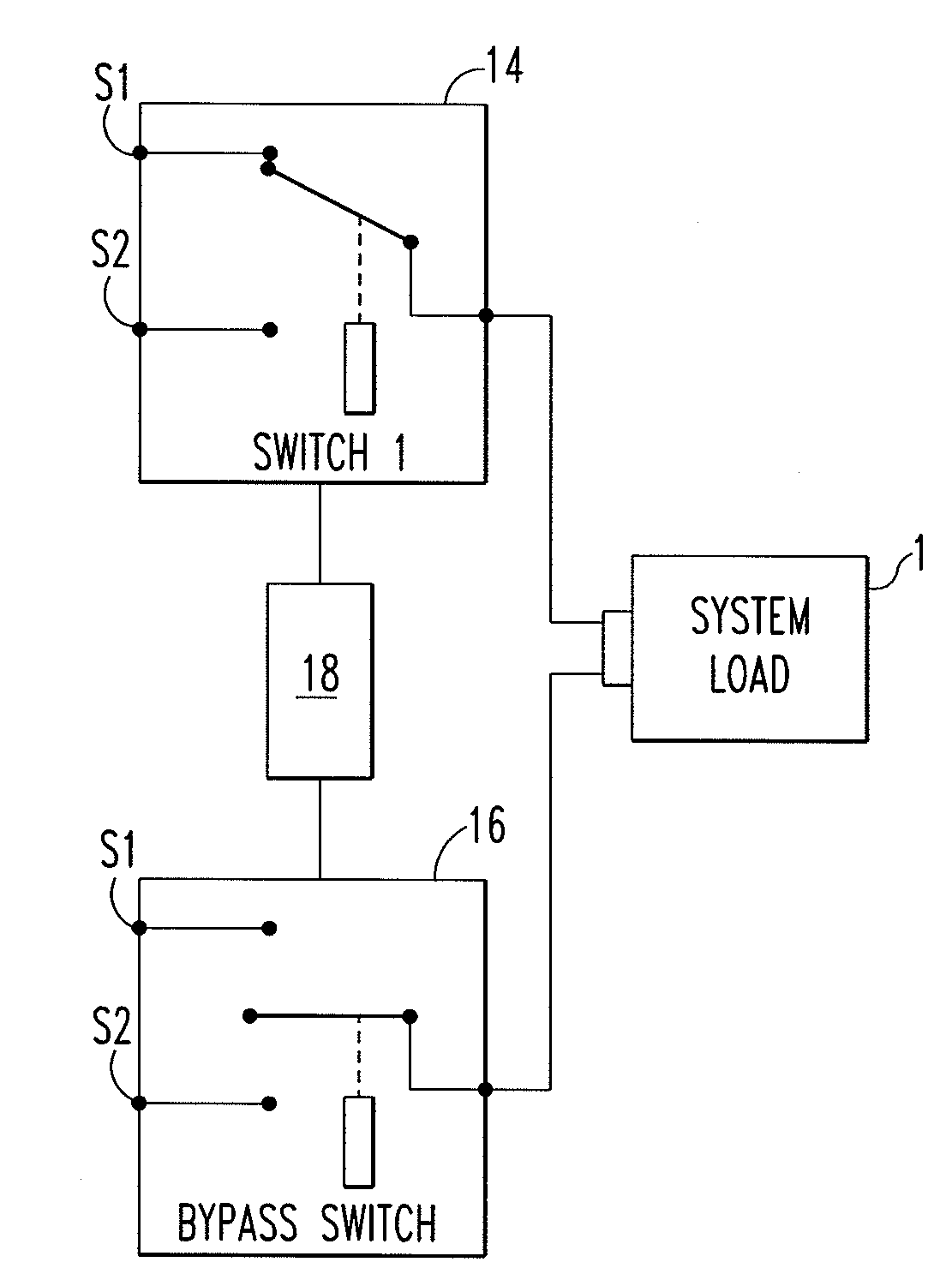
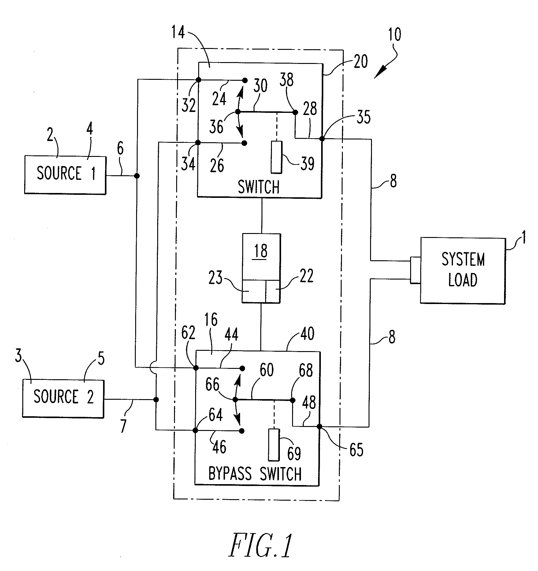
[0024]As used herein, a “system load” is any load downstream of a transfer switch assembly but is, typically, a large installation such as, but not limited to, a building or manufacturing plant.

[0025]As ...


PUM


Abstract

The disclosed concept provides for a closed transition automatic transfer switch assembly having only two switch assemblies. This system utilizes a first switch assembly and a bypass switch assembly. The switch assemblies are each physically coupled to two power sources as well as the system load. The switch assemblies each include a power actuated contact arm. Each contact arm is coupled to, and in electrical communication with, the system load. Each contact arm may further be placed in one of the following configuration; a first configuration wherein the contact arm couples, and provides electrical communication between, the first source and the system load conductor, a second configuration wherein the contact arm couples, and provides electrical communication between, the second source and the system load conductor, and a neutral configuration wherein neither the first source nor the second source is coupled to, and in electrical communication with, the system load conductor.

Description

BACKGROUND OF THE INVENTION[0001]1. Field of the Invention[0002]This invention relates to a closed transition automatic transfer switch assembly and, more specifically, a closed transition automatic transfer switch assembly having only two switches.[0003]2. Background Information[0004]Certain installations, e.g. hospitals, (hereinafter “the system load”) must have power systems structured to provide an uninterruptable power supply. The primary power source is typically the public power grid and the secondary power source is typically a generator. Both of these sources are structured to provide power over an extended period of time. That is, the system typically draws power from the primary power source, however, if that source becomes disabled for an extended period of time, the secondary source is used. A third power supply, a continuous power supply (CPS), such as a fuel cell backup or battery backup is structured to maintain power to the system during short power interruptions, e...

Claims


Application Information

Patent Timeline
IPC IPC(8): H02H3/42
CPCH02J9/06
Inventor GIBBS, IRVING A.HOGLUND, JUSTINCLAUSEN, CATHLEENYANNIELLO, ROBERTMULEY, AVADHOOTLATHROP, TODD M.
Owner EATON CORP
Features
  • Generate Ideas
  • Intellectual Property
  • Life Sciences
  • Materials
  • Tech Scout
  • Unparalleled Data Quality
  • Higher Quality Content
  • 60% Fewer Hallucinations
Learn More