Frequency multiplier and method for frequency multiplying

a frequency multiplier and frequency technology, applied in the field of frequency converters, can solve problems such as complex conventional frequency multipliers, and achieve the effect of low cost and simple structur

Inactive Publication Date: 2010-06-10
FAIRCHILD TAIWAN
View PDF6 Cites 15 Cited by
  • Summary
  • Abstract
  • Description
  • Claims
  • Application Information

AI Technical Summary

Benefits of technology

[0005]An object of the present invention is to provide a simple and lo

Problems solved by technology

The conventional frequen

Method used


Image

  • Frequency multiplier and method for frequency multiplying
  • Frequency multiplier and method for frequency multiplying
  • Frequency multiplier and method for frequency multiplying

Examples


Embodiment Construction

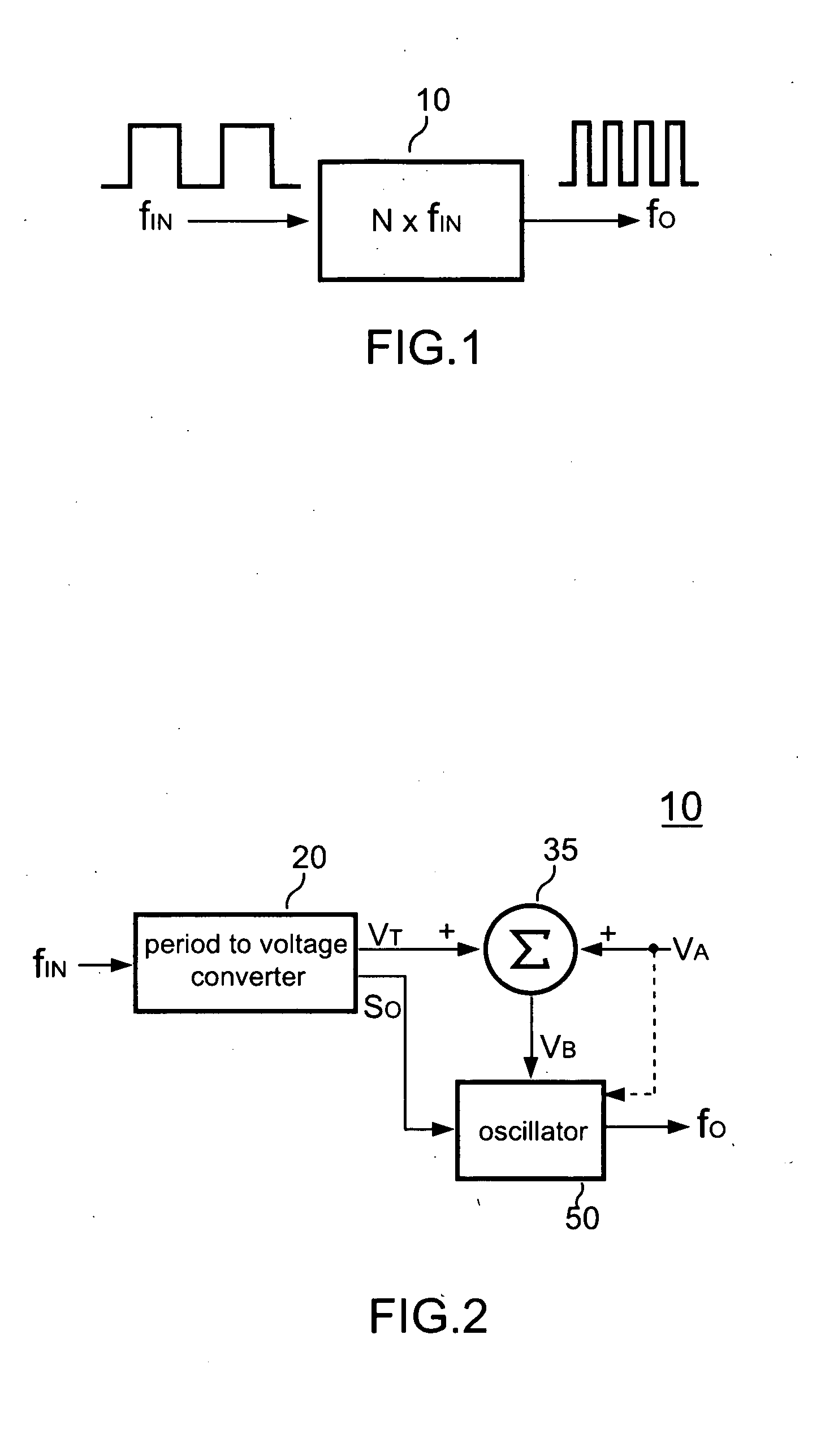
[0017]FIG. 1 shows the circuit schematic of a frequency multiplier according to the present invention. An input signal fIN is coupled to the input of the frequency multiplier10. The frequency multiplier 10 (generates an output signal fO with a frequency of the input signal fIN multiplied by N.

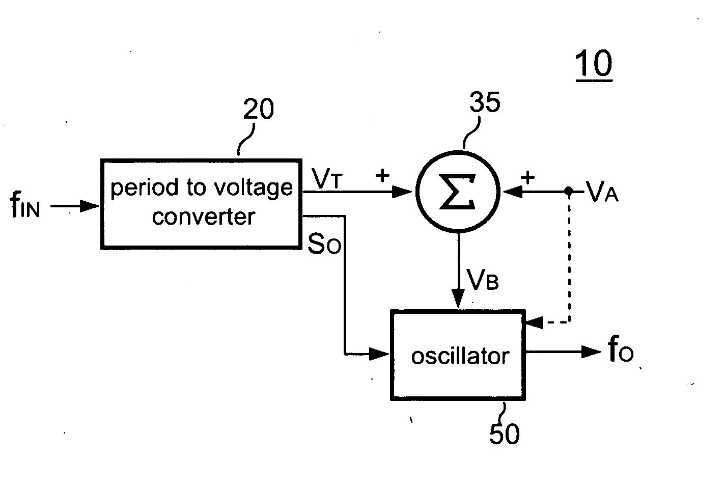
[0018]FIG. 2 shows the block diagram of a preferred embodiment of the frequency multiplier 10 of the present invention. The frequency multiplier 10 comprises a period-to-voltage converter 20 and an oscillator 50. The period-to-voltage converter 20 generates a control signal VT in response to the period of the input signal fIN. The level of the control signal VT is corrected to the frequency of the input signal fIN. It means that the level of the control signal VT is also corrected to the period of the input signal fIN. The oscillator 50 generates the output signal fO in accordance with the control signal VT. The control signal VT is coupled to the oscillator 50 and operate as a trip-point volta...


PUM


Abstract

A frequency multiplier according to the present invention comprises a period-to-voltage converter that generates a control signal in response to the period of an input signal. An oscillator generates an output signal in accordance with the control signal. The level of the control signal is corrected to the frequency of the input signal. The control signal is coupled to determine the frequency of the output signal.

Description

BACKGROUND OF THE INVENTION[0001]1. Filed of Invention[0002]The present invention relates to a frequency converter, and more particularly, to the frequency multiplier and method for frequency multiplying.[0003]2. Description of Related Art[0004]A frequency multiplier is commonly used to multiply the base frequency for generating a high frequency clock signal, it can be used to many electronic devices, such as the BLDC motor controllers and the synchronized switching of DC / DC buck / boost converters, etc. The conventional frequency multiplier is complex.SUMMARY OF THE INVENTION[0005]An object of the present invention is to provide a simple and low cost circuit for the frequency multiplier and a method used therein.[0006]A frequency multiplier according to a preferred embodiment of the present invention includes a period-to-voltage converter generating a control signal in response to the period of an input signal. An oscillator generates an output signal in accordance with the control s...

Claims


Application Information

Patent Timeline
IPC IPC(8): H03B19/00
CPCH03K5/00006
Inventor YANG, TA-YUNGTSU, PEI-SHENGLIN, CHIH-HOLI, CHUAN-CHANG
Owner FAIRCHILD TAIWAN
Why Eureka
Try Eureka