
Sleep alert device

a technology of alert device and sleep, which is applied in the direction of alarms, instruments, vehicle components, etc., can solve the problems of motor vehicle drivers, drivers, and drivers who put in long grueling hours at the wheel of their vehicles, and achieve the effects of simple use, cost saving, and easy repositioning

Inactive Publication Date: 2010-06-10
POWER JEROME ARNOLD
View PDF15 Cites 13 Cited by
  • Summary
  • Abstract
  • Description
  • Claims
  • Application Information

AI Technical Summary

Benefits of technology

[0012]It is an object of the present invention to provide a novel device that has addressed the above problems along with other benefits to the user which will become evident from the disclosure and examples described herein. The present invention is relatively simple to use, activates immediately if a driver starts to nod off, can easily be turned off for repositioning or other activities, and is cost effective compared to other systems.

Problems solved by technology

Drivers of motor vehicles, especially truck drivers, often put in long grueling hours at the wheel of their vehicle.
It is not surprising then that motor vehicle accidents occur where the driver has dozed off at the wheel and where the vehicle has veered off the road.
Accidents result not only in vehicle damage, property damage, and severe injury or death of the driver; it can also result in the death or injury of other drivers or pedestrians in the area of the accident.
Accidents that occur when the driver falls asleep at the wheel often have a high percentage of fatality.
NHTSA conservatively estimates fatigue-related crashes result in an estimated 1,550 deaths, 71,000 injuries, and $12.5 billion in monetary losses each year.
Contact is measured by the driver's skin resistance rather than pressure, and has been considered unreliable since the ambient temperature differences effect perspiration, and thus, alter skin resistance readings.
While it is clear that each of these devices fulfill a particular objective or requirement, it is clear that each has particular limitations, and in general, are either extraordinarily complex or do not activate an alarm until the driver has already started to dose off.

Method used


Image

  • Sleep alert device
  • Sleep alert device
  • Sleep alert device

Examples


Embodiment Construction

[0022]While this invention is susceptible to embodiment in many different forms, there is shown in the drawings, and will herein, be described in detail specific embodiments, with the understanding that the present disclosure of such embodiments is to be considered as an example of the principles, and not intended to limit the invention to the specific embodiments shown and described. In the description below, like reference numerals are used to describe the same, similar, or corresponding parts in the several views of the drawings. This detailed description defines the meaning of the terms used herein, and specifically describes embodiments in order for those skilled in the art to practice the invention.

DEFINITIONS

[0023]The terms “a” or “an”, as used herein, are defined as one or as more than one. The term “plurality”, as used herein, is defined as two or as more than two. The term “another”, as used herein, is defined as at least a second or more. The terms “including” and / or “hav...


PUM


Abstract

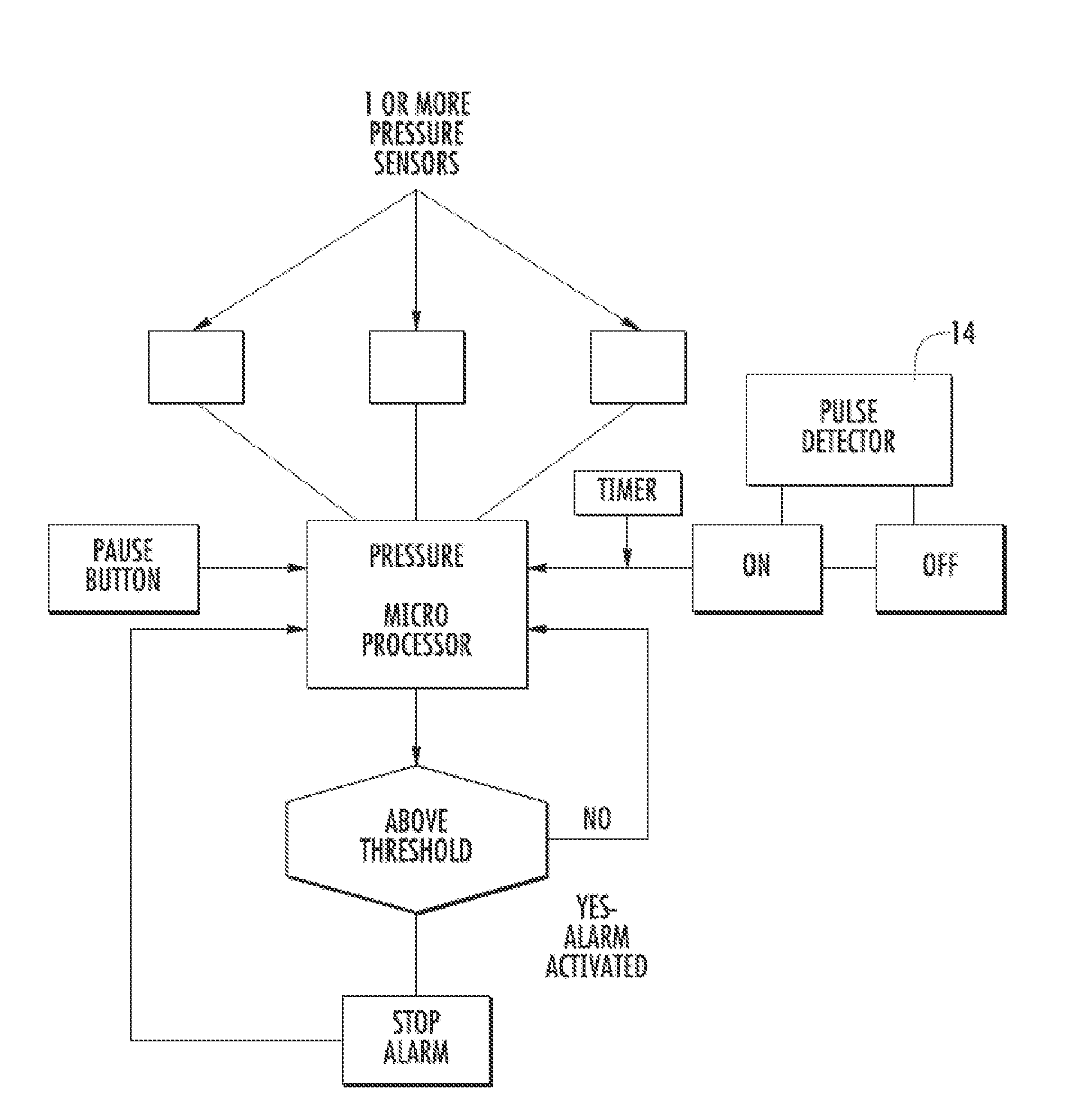
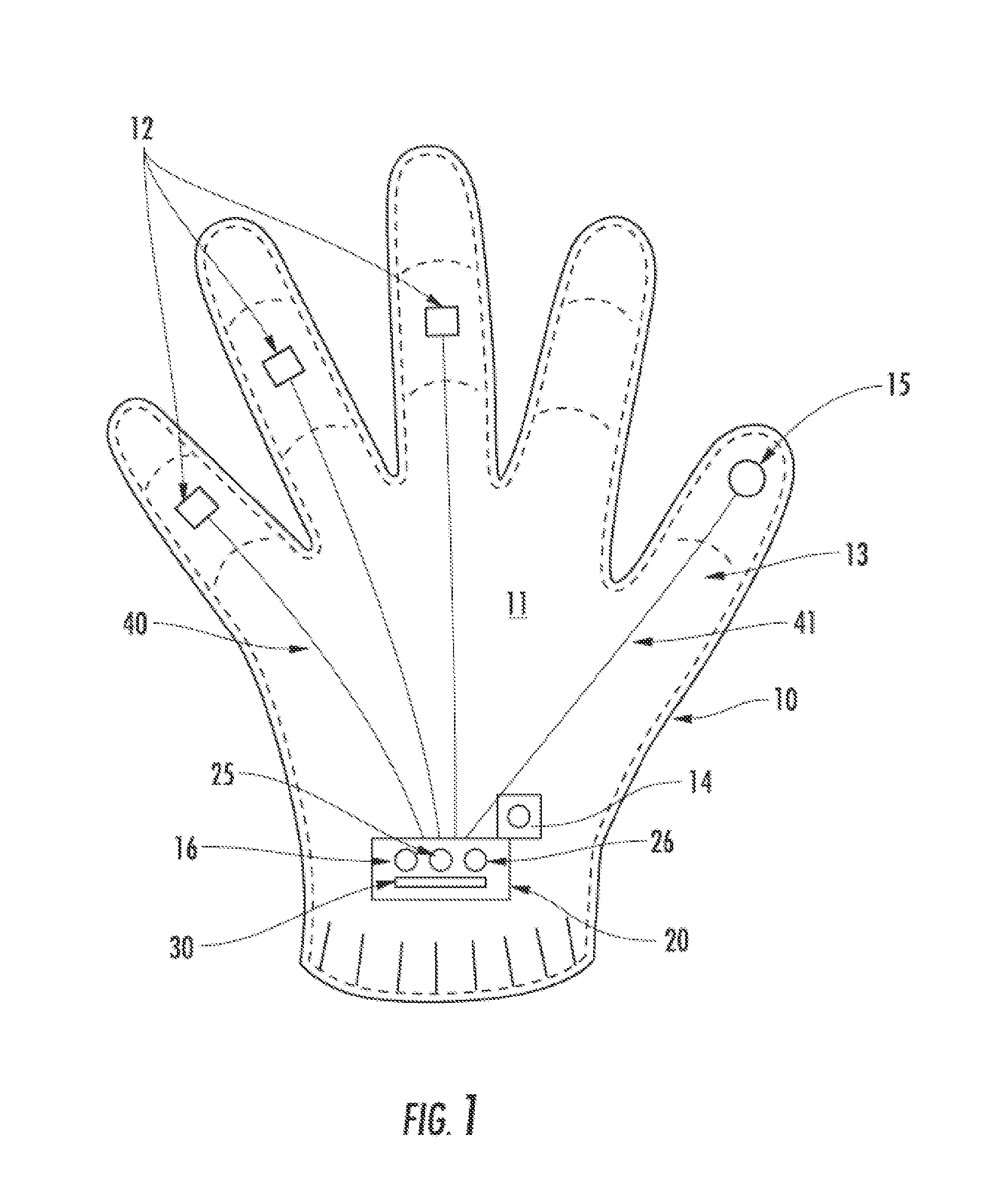
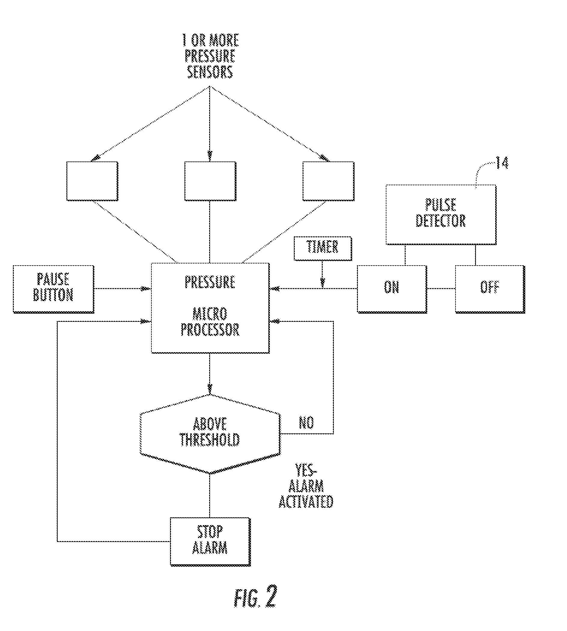
The present invention relates to a sleep alert device that acts by pressure of the fingers of the user on sensors. The invention includes a limited number of sensors as well as an instant alarm system which prevents accidental problems with previous delay alarm systems. At least one sensor is mounted on the fingers of the user or the steering wheel and with no delay of any kind connected directly or wirelessly to a control panel for control of the pressure sensors. The device has a means for detecting the wearing by the user, such as a pulse detector which can tell if the device is on or off when a pulse is detected respectively.

Description

CROSS-REFERENCE TO RELATED APPLICATIONS[0001]This application is a continuation-in-part of U.S. patent application Ser. No. 11 / 391,652 filed on Mar. 28, 2006 and is included herein in its entirety by reference.COPYRIGHT NOTICE[0002]A portion of the disclosure of this patent contains material that is subject to copyright protection. The copyright owner has no objection to the reproduction by anyone of the patent document or the patent disclosure as it appears in the Patent and Trademark Office patent files or records, but otherwise reserves all copyright rights whatsoever.BACKGROUND OF THE INVENTION[0003]1. Field of the Invention[0004]The present invention relates to sleep detection warning devices and more particularly, it pertains to a novel sleep alert warning system for waking a dozing driver.[0005]2. Description of Related Art[0006]Drivers of motor vehicles, especially truck drivers, often put in long grueling hours at the wheel of their vehicle. Because of the need or desire to...

Claims


Application Information

Patent Timeline
IPC IPC(8): B60Q1/00
CPCG08B21/06B60K28/06
Inventor POWER, JEROME ARNOLD
Owner POWER JEROME ARNOLD
Learn More