Display device and aging method

a display device and aging technology, applied in the field of display devices and aging methods, can solve the problems of long aging period and require aging of organic el display devices, and achieve the effect of shortening the aging period

Inactive Publication Date: 2010-06-10
HITACHI DISPLAYS +1
View PDF3 Cites 3 Cited by
  • Summary
  • Abstract
  • Description
  • Claims
  • Application Information

AI Technical Summary

Benefits of technology

[0019]The display device and aging method according to the present invention make it possible to shorten the aging period.

Problems solved by technology

Meanwhile, organic EL display devices require aging.
In conventional organic EL display devices having a capacitor direct connection type pixel circuit, however, an image voltage of the maximum level is written into one display line unit during the write-in period (T-DW), as shown in FIG. 2A, so that the organic EL display device ages while emitting light at the maximum brightness during the light emitting period (T-LU), and thus, there is a problem, such that the aging period becomes long.

Method used


Image

  • Display device and aging method
  • Display device and aging method
  • Display device and aging method

Examples


first embodiment

[0033]FIG. 3 is a circuit diagram showing one pixel in the organic EL display panel according to the first embodiment of the present invention, and an equivalent circuit in the peripheral portion.

[0034]A number of pixels (PIX) are provided in a matrix within the display region on the organic EL display panel of the organic EL display device according to the present embodiment. A signal line 11, a reset line 12, a turn on switch line 13, a power supply line 14 and an aging control line 20 are connected to each pixel (PIX). The signal line 11, the reset line 12 and the turn on switch line 13 are connected to the below described drive circuit (DRV).

[0035]The drive circuit (DRV) supplies a drive voltage to the reset line 12 and the turn on switch line 13 and selects a display line. In addition, the drive circuit DRV converts digital video data supplied from outside the organic EL display panel to an analog video voltage in series, which is then supplied to the signal line 11.

[0036]All o...

second embodiment

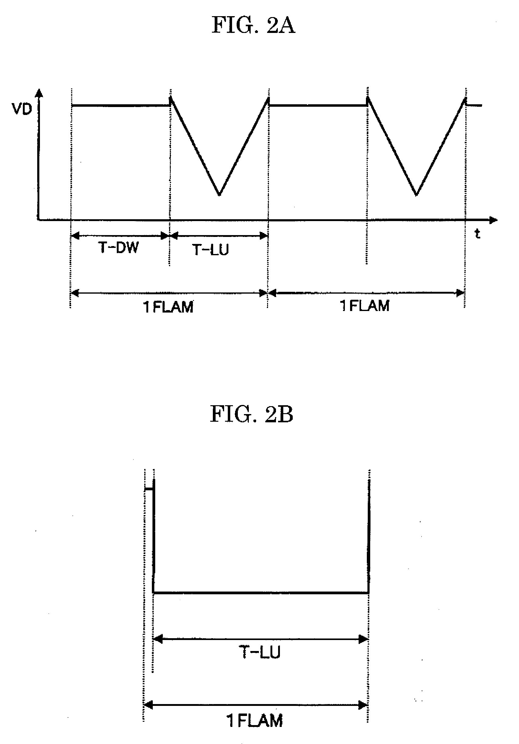
[0068]FIGS. 6A and 6B are diagrams illustrating the aging method for an organic EL display device according to the second embodiment of the present invention.

[0069]In some cases, the organic EL element 1 has different optimal aging conditions for light of different colors: R (red), G (green) and B (blue).

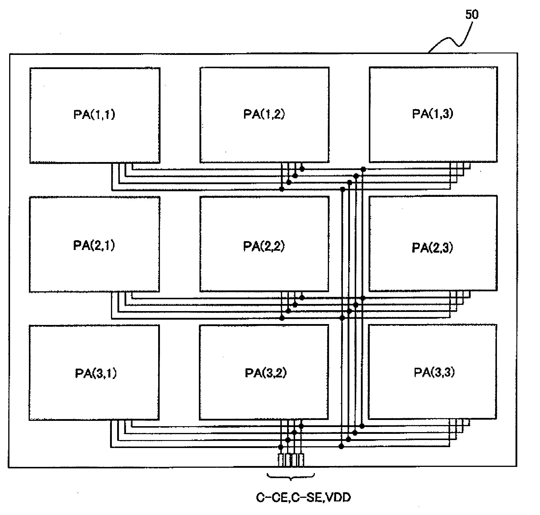
[0070]In the present embodiment, as shown in FIG. 6A, the aging control signal (S-CE) is divided for each color: R, G and B, so that each can be aged for the optimal aging time.

[0071]As shown in FIG. 7A, terminals are formed in the peripheral portion of the organic EL display panel. As shown in FIG. 7B showing an enlargement of the circled portion in FIG. 7A, the terminals in the peripheral portion include a terminal group (T-COL) for carrying out inspection in a state where no drive circuit (DRV) is mounted, in addition to a terminal group (T-COG) used after a drive circuit (DRV) is mounted.

[0072]Therefore, as shown in FIG. 6B, in the present embodiment, the terminal group (T-COL) ...

third embodiment

[0075]FIG. 8 is a diagram for illustrating the aging method for an organic EL display device according to the third embodiment of the present invention.

[0076]FIG. 8 is a wire diagram showing a case where the drive circuit (DRV) outputs an aging control signal after the drive circuit (DRV) is mounted and aging is carried out under optimal aging conditions for light of each color: F (red), G (green) and B (blue).

[0077]In the present embodiment, aging is carried out on the basis of the aging control signal outputted from the drive circuit (DRV) after the drive circuit (DRV) is mounted, and therefore, the second transistor (Q11) is not necessary, and thus, the aging control signal switching signal line 22 and the aging control signal lines (21, 21R, 21G, 21B) are not necessary.

[0078]Therefore, as shown in FIG. 8, the structure in the peripheral portion is simple, and the drive circuit (DRV) needs to have a function of outputting both an aging control signal at an H level and an aging co...


PUM


Abstract

The display device according to the present invention is provided with a thin film transistor (first transistor) for aging which directly connects an organic EL element to a power supply line, and furthermore, an aging control line and a thin film transistor (second transistor) for switching aging control signals are provided in order to control the thin film transistor for aging, and thus the aging period is shorter.

Description

CROSS-REFERENCE TO RELATED APPLICATION[0001]The present application claims priority over Japanese Application JP2008-312348 filed on Dec. 8, 2008, the contents of which are hereby incorporated into this application by reference.BACKGROUND OF THE INVENTION[0002](1) Field of the Invention[0003]The present invention relates to a display device and an aging method, and in particular, to an aging method for an active matrix type display device using organic electroluminescent elements as light emitting elements.[0004](2) Description of the Related Art[0005]Organic EL display devices with an active matrix using organic electroluminescent elements (hereinafter referred to as organic EL elements) as light emitting elements are expected to become next-generation flat panel displays.[0006]In such active matrix type organic EL display devices, wires for transmitting a video voltage and current are wired in a matrix and a pixel circuit formed of a thin film transistor (hereinafter referred to a...

Claims


Application Information

Patent Timeline
Patent Type & Authority Applications(United States)
IPC IPC(8): G06F3/038G09G5/10
CPCG09G2300/0809G09G3/3233G09G2310/0259
Inventor FURUIE, MASAMITSU
Owner HITACHI DISPLAYS
Why Eureka
Try Eureka