Method And Device Using Rotating Printing Arm To Project Or View Image Across A Workpiece

a technology of rotating printing arm and workpiece, which is applied in the direction of photomechanical equipment, instruments, optical elements, etc., can solve the problems of increasing the difficulty of writing, affecting the reliability and performance of the serviced reading and writing head, and bending the cables and support members

Active Publication Date: 2010-06-10
MICRONIC LASER SYST AB
View PDF10 Cites 87 Cited by
  • Summary
  • Abstract
  • Description
  • Claims
  • Application Information

AI Technical Summary

Problems solved by technology

Bending of cables and support members can impact both reliability and performance.
Some serviced reading and writing heads are heavy, bulky or otherwise...

Method used


Image

  • Method And Device Using Rotating Printing Arm To Project Or View Image Across A Workpiece
  • Method And Device Using Rotating Printing Arm To Project Or View Image Across A Workpiece
  • Method And Device Using Rotating Printing Arm To Project Or View Image Across A Workpiece

Examples


Embodiment Construction

[0031]The following detailed description is made with reference to the figures. Preferred embodiments are described to illustrate the disclosed technology, not to limit its scope, which is defined by the claims. Those of ordinary skill in the art will recognize a variety of equivalent variations on the description that follows.

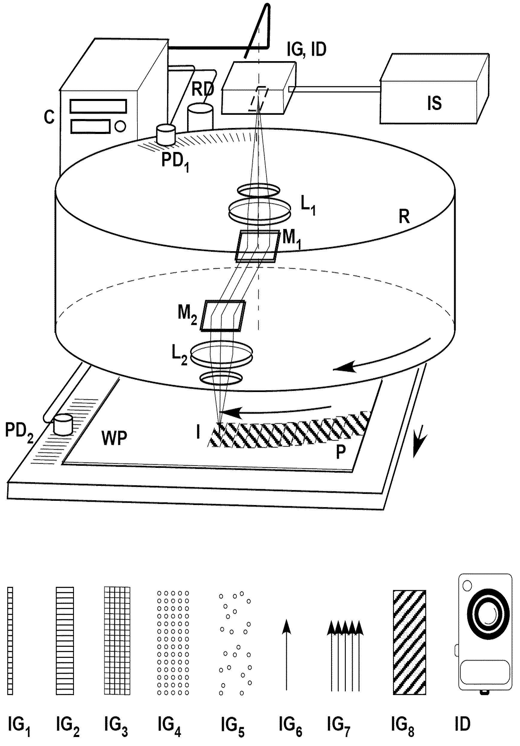
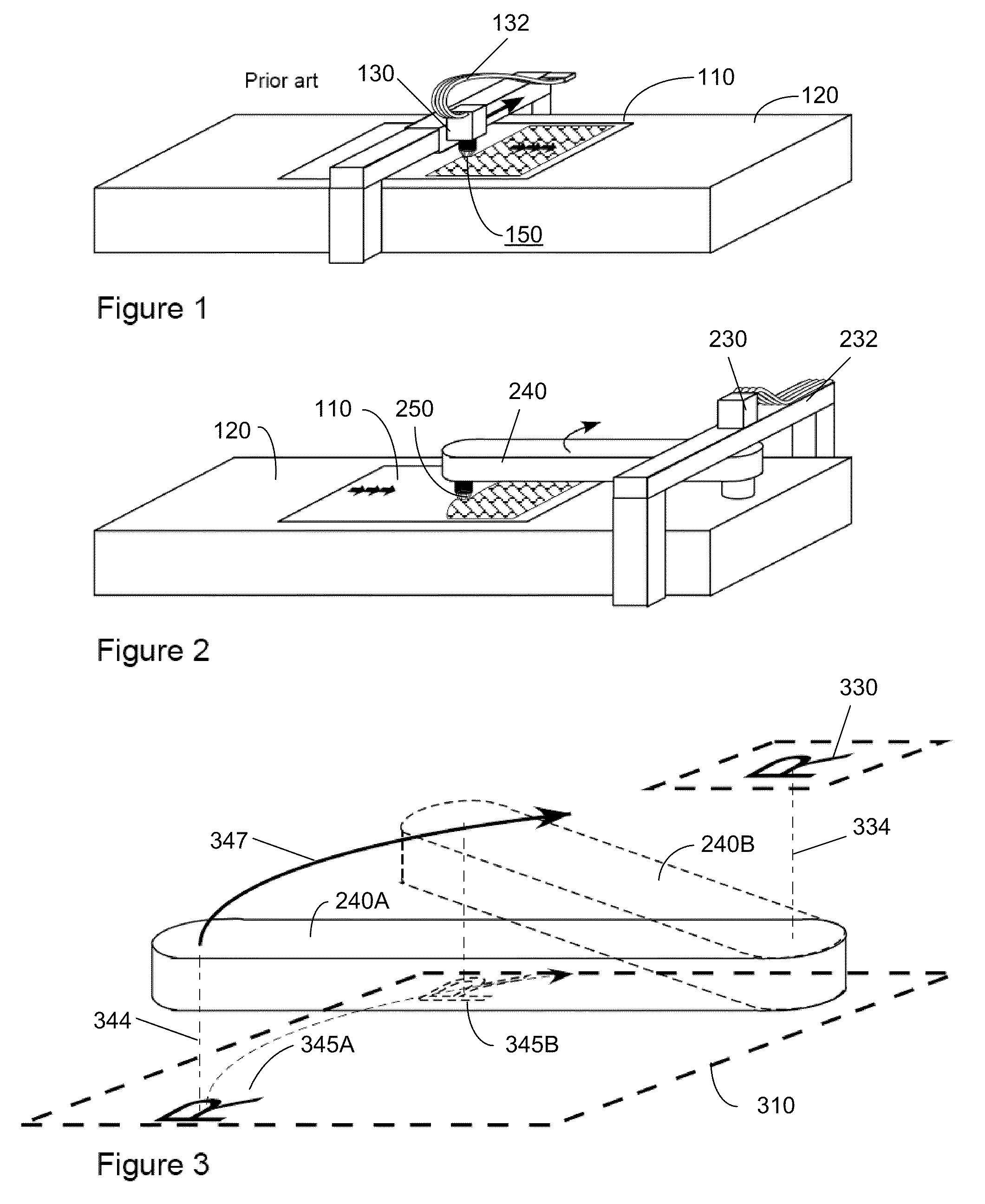
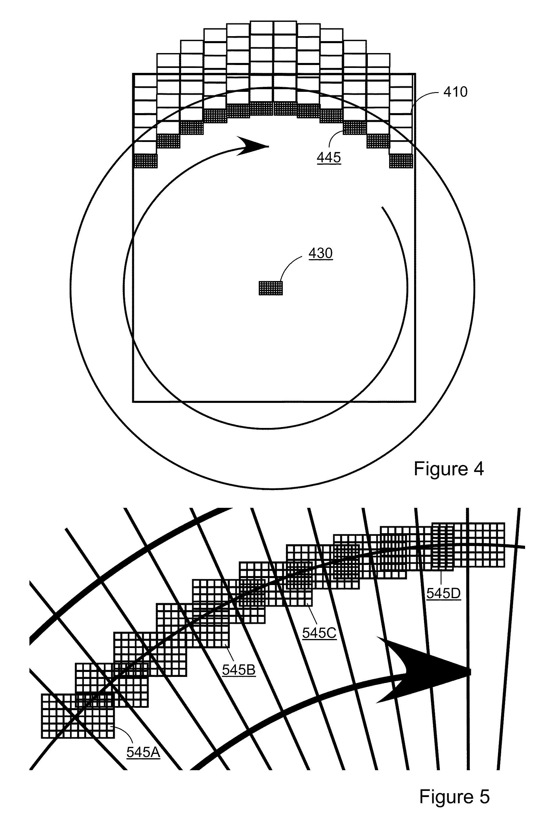
[0032]This disclosure covers embodiments of a rotating arm printing or viewing device with relay optics with a hub at one end of the arm and optics at the other end, which couple image information with the surface of a workpiece. The optical coupling at the hub may be either on or off the axis of rotation.

[0033]In certain embodiments, the disclosed technology provides for a method and apparatus for writing to (or reading from) a workpiece, including using a stationary optical image device to form (or collect) relayed image information and further relaying the image information along optics of at least one rotating arm between the stationary optical image devic...


PUM


Abstract

The technology disclosed relates to scanning of large flat substrates for reading and writing images. Examples are flat panel displays, PCB's and photovoltaic panels. Reading and writing is to be understood in a broad sense: reading may mean microscopy, inspection, metrology, spectroscopy, interferometry, scatterometry, etc. of a large workpiece, and writing may mean exposing a photoresist, annealing by optical heating, ablating, or creating any other change to the surface by an optical beam. In particular, we disclose a technology that uses a rotating or swinging arm that describes an arc across a workpiece as it scans, instead of following a traditional straight-line motion.

Description

RELATED APPLICATIONS[0001]This application claims the benefit of U.S. Provisional Patent Application No. 61 / 200,970, entitled, “Method and Device Using Rotating Printing Arm to Project or View Image Across a Workpiece,” filed on Dec. 5, 2008.BACKGROUND OF THE INVENTION[0002]The technology disclosed relates to scanning of large flat substrates for reading and writing images. Examples are flat panel displays, Printed Circuit Boards (PCBs) and photovoltaic panels. Reading and writing is to be understood in a broad sense: reading may mean microscopy, inspection, metrology, spectroscopy, interferometry, scatterometry, etc. of a large workpiece, and writing may mean exposing a photoresist, annealing by optical heating, ablating, or creating any other change to the surface by an optical beam. In particular, we disclose a technology that uses a rotating or swinging arm that describes an arc across a workpiece as it scans, instead of following a traditional straight-line motion.[0003]FIG. 1 ...

Claims


Application Information

Patent Timeline
IPC IPC(8): G06T7/00H04N1/04
CPCG02B26/105G03F7/70291B41J2/47G03F7/70391G03F7/704G03F7/70366
Inventor SANDSTROM, TORBJORNLINDAU, STEN
Owner MICRONIC LASER SYST AB
Why Eureka
Try Eureka