Dynamic performance monitoring systems and methods for optical networks

a dynamic performance monitoring and optical network technology, applied in the field of optical networks, can solve the problems of limited pre-fec bit error rate (ber) accuracy at high values, limited current state of optical fiber and installed equipment, and inability to accurately estimate optical channel performance characteristics

Active Publication Date: 2010-06-10
CIENA
View PDF42 Cites 80 Cited by
  • Summary
  • Abstract
  • Description
  • Claims
  • Application Information

AI Technical Summary

Benefits of technology

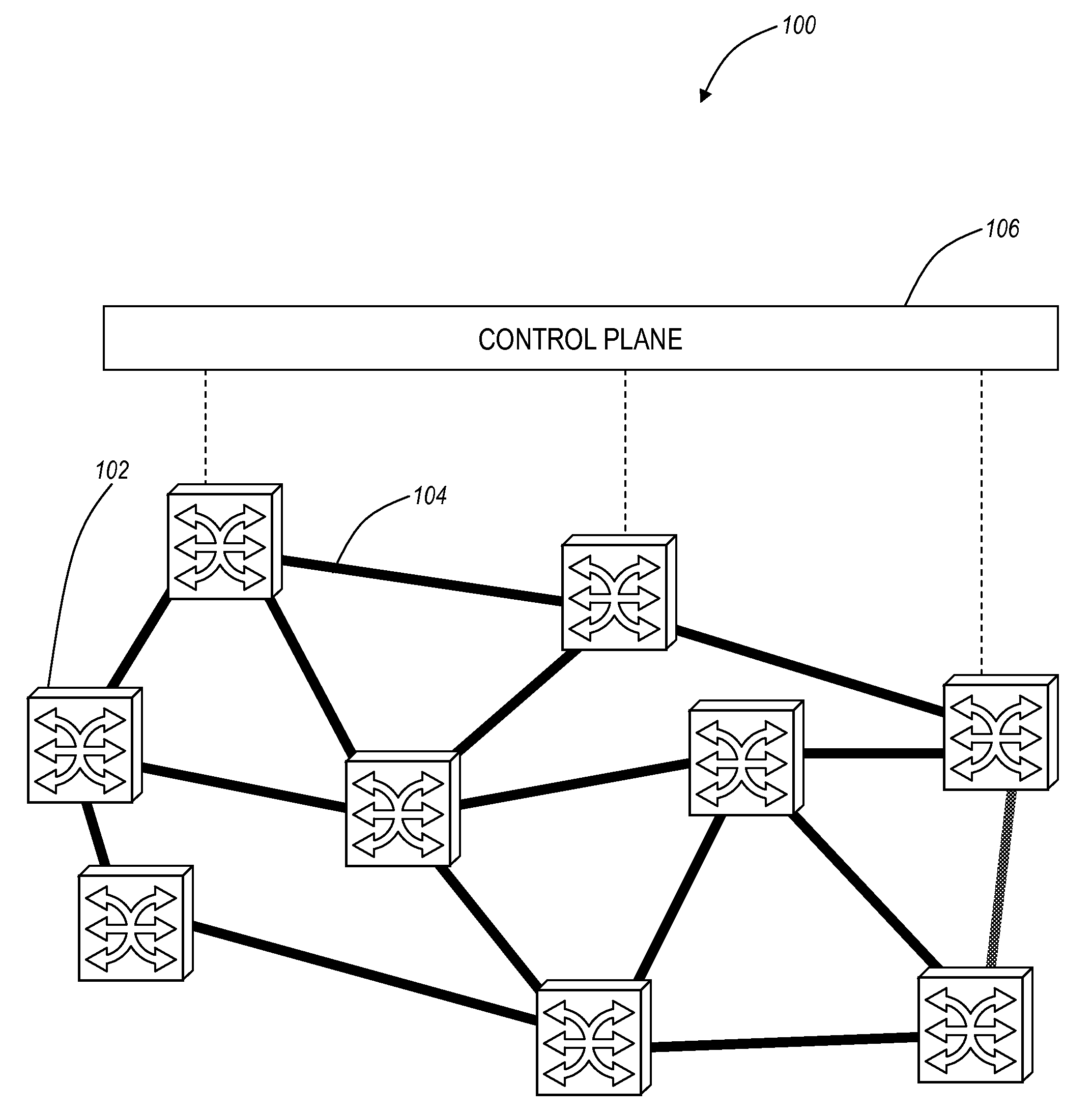
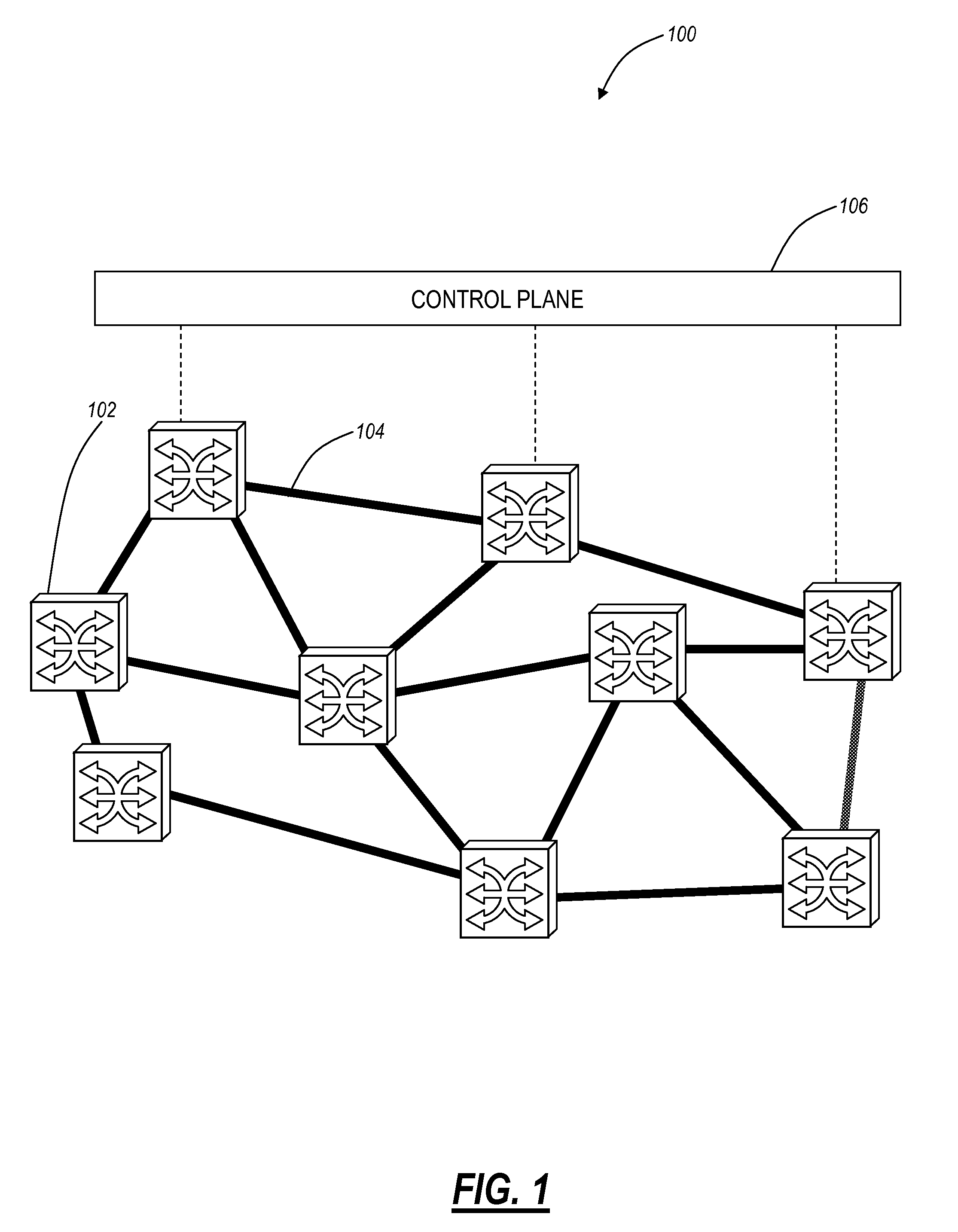
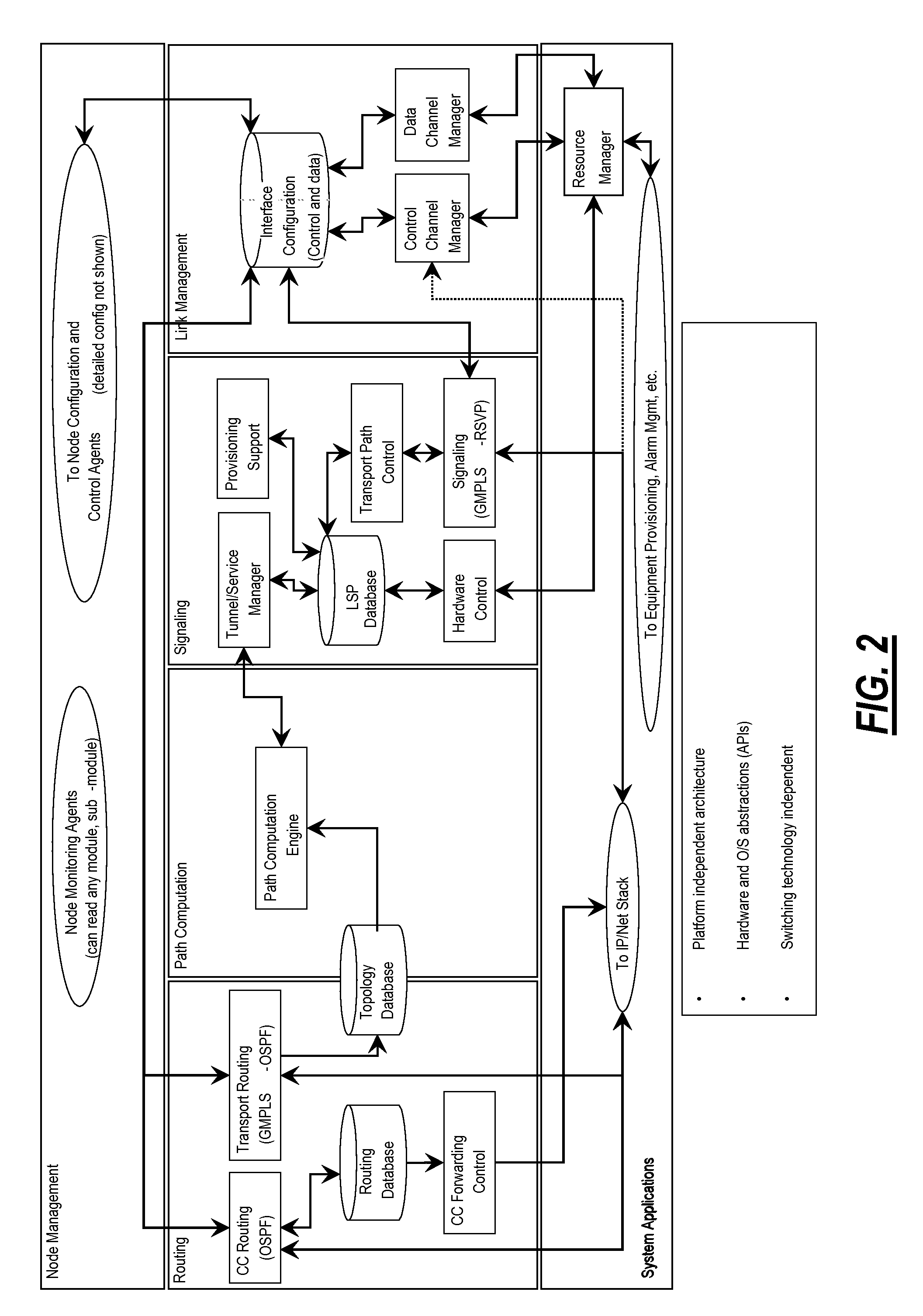
[0014]In an exemplary embodiment of the present invention, an optical network includes: a plurality of nodes interconnected through a plurality of links; a control plane communicatively coupled to each of the plurality of nodes; wherein the control plane includes an optical path computation function configured to provide estimation of optical channel performance characteristics. The optical channel performance characteristics include any of OSNR measurement, residual Chromatic Dispersion, Polarization Dependent Loss, Polarization Mode Dispersion, inter-channel nonlinear effects, intra-channel nonlinear effects, and bandwidth narrowing. The optical network further includes a plurality of optical probes distributed through the optical network, wherein each of the optical probes is configured to provide the optical channel performance characteristics. Each of the optical probes includes a Homodyne Coherent receiver with a digital post-processor, the Homodyne Coherent receiver configured to directly measure an incident electrical field amplitude and phase; and a transmitter. The digital post-processor includes filter coefficients utilized to determine a level of residual Chromatic Dispersion, Polarization Dependent Loss, Polarization Mode Dispersion, and bandwidth narrowing; and wherein the digital post-processor is configured to apply reverse Schrödinger propagation to estimate intra-channel nonlinear effects. The transmitter includes a tunable laser coupled to a modulator coupled to a selectable rate oscillator; wherein the transmitter generates internal data and transmission properties of the transmitter are programmably modifiable. The optical network can further include a polariza

Problems solved by technology

These must still be validated against field measurements, as there are large uncertainties in the optical fiber and installed equipment as well as possible aging errors.
The current state of the art in deployed networks is limited to three types of measurements.
Further, pre-FEC bit error rate (BER) is only accurate at high values.
Finally, n

Method used


Image

  • Dynamic performance monitoring systems and methods for optical networks
  • Dynamic performance monitoring systems and methods for optical networks
  • Dynamic performance monitoring systems and methods for optical networks

Examples


Embodiment Construction

[0026]In various exemplary embodiments, the present invention provides dynamic performance monitoring systems and methods for optical networks that allow optical network health to be ascertained in a flexible and accurate manner. The present invention introduces accurate estimations for optical channel performance characteristics based either on existing channels or with a dynamic optical probe configured to measure characteristics on unequipped wavelengths. Advantageously, the dynamic performance monitoring systems and methods introduce the ability to determine physical layer viability in addition to logical layer viability.

[0027]The present invention includes an optical probe element positioned at various points throughout the optical network. The optical probe includes a transmitter and receiver portion. The transmitter portion of the probe produces an optical pulse train modulated with PRBS data, and with a tunable wavelength and duty cycle and repetition rates selectable to rep...


PUM


Abstract

The present disclosure provides dynamic performance monitoring systems and methods for optical networks to ascertain optical network health in a flexible and accurate manner. The present invention introduces accurate estimations for optical channel performance characteristics based either on existing channels or with a dynamic optical probe configured to measure characteristics on unequipped wavelengths. Advantageously, the dynamic performance monitoring systems and methods introduce the ability to determine physical layer viability in addition to logical layer viability.

Description

CROSS-REFERENCE TO RELATED APPLICATION[0001]The present non-provisional patent application / patent claims the benefit of priority of co-pending U.S. Provisional Patent Application No. 61 / 120,649, filed on Dec. 8, 2008, and entitled “DYNAMIC PERFORMANCE MONITORING SYSTEMS AND METHODS FOR OPTICAL NETWORKS,” the contents of which are incorporated in full by reference herein.FIELD OF THE INVENTION[0002]The present invention relates generally to optical networks and systems and methods for monitoring and assessing the performance of the same. More particularly, the present invention provides dynamic performance monitoring systems and methods for optical networks that allow optical network health to be ascertained in a flexible and accurate manner. The configuration and performance of the optical networks may then be adjusted accordingly to achieve desired characteristics and / or performance goals. Thus, the present invention provides valuable diagnostic tools.BACKGROUND OF THE INVENTION[00...

Claims


Application Information

Patent Timeline
IPC IPC(8): H04B10/08
CPCH04B10/0795H04J14/0257H04J14/0258H04J14/0284H04J14/0269H04J14/0271H04J14/0268
Inventor FRANKEL, MICHAEL Y.BLAIR, LOUDON T.BOURGET, CHRISTIANONG, LYNDON Y.
Owner CIENA
Why Eureka
Try Eureka