
Machine learning device learning failure occurrence mechanism of laser device

a laser device and machine learning technology, applied in the field of machine learning devices, can solve the problems of not performing machine learning for quantitative failure occurrence mechanisms of apparatus for diagnosing abnormalities, insufficient accuracy, and large quantity of failure data collection, etc., to achieve the effect of enhancing learning accuracy, enhancing learning progress speed, and prolonging learning tim

Active Publication Date: 2021-04-27
FANUC LTD
View PDF9 Cites 0 Cited by
  • Summary
  • Abstract
  • Description
  • Claims
  • Application Information

AI Technical Summary

Benefits of technology

The machine learning device described in this patent can identify the specific mechanism that causes failures in a system and predict when they will occur with high accuracy. This is compared to traditional methods that just look at statistical data. Additionally, the machine learning device can work with a network-connected laser device to prevent failures and increase reliability.

Problems solved by technology

On the other hand, since a failure does not occur so often, it is hard to obtain sufficient quantity of data.
As a result, there has been a problem that even though a failure occurrence cause and a failure occurrence condition are learned through machine learning in a manner to associate a result which is the failure state with state variables of a laser device obtained on the time point on which the failure occurs and before and after the failure occurrence, sufficient accuracy cannot be obtained or much time is required to collect large quantity of failure data and improve accuracy.
However, though the apparatus for diagnosing abnormality specifies a state variable causing abnormality, the apparatus for diagnosing abnormality does not perform machine learning for quantitative failure occurrence mechanisms.
Thus, Japanese Patent Application Laid-Open No. 2017-030221 does not make mention of physical evidence coupling an abnormality cause with an abnormality phenomenon, and as a result, Japanese Patent Application Laid-Open No. 2017-030221 does not show a solution to the problem that sufficient accuracy cannot be obtained even through machine learning due to presence of many state variables and few failure occurrence case examples and much time is required until large quantity of failure data are collected and accuracy is improved.
However, according to Japanese Patent Application Laid-Open No. 2017-033526 mentioned above, the learning unit learns a condition associated with a failure, but the learning unit does not perform machine learning for quantitative failure occurrence mechanisms.
Thus, Japanese Patent Application Laid-Open No. 2017-033526 does not make mention of physical evidence coupling an abnormality cause with an abnormality phenomenon, and Japanese Patent Application Laid-Open No. 2017-033526 does not show a solution to the problem that sufficient accuracy cannot be obtained even through machine learning due to presence of many state variables and few failure occurrence case examples and much time is required until large quantity of failure data are collected so that accuracy is improved.
However, though this health management system quantifies a health state of the machine plant by the statistical method using normal data as learning data, the health management system does not perform machine learning for quantitative failure occurrence mechanisms.
Further, Japanese Patent Application Laid-Open No. 2015-088079 does not make mention of physical evidence coupling an abnormality cause with an abnormality phenomenon, and Japanese Patent Application Laid-Open No. 2015-088079 thus does not show a solution to the problem that sufficient accuracy cannot be obtained even through machine learning due to presence of many state variables and few failure occurrence case examples and much time is required until large quantity of failure data are collected so that accuracy is improved.
However, any of those patent documents does not show a solution to the problem that sufficient accuracy cannot be obtained even through machine learning due to presence of many state variables and few failure occurrence case examples and much time is required until large quantity of failure data are collected so that accuracy is improved.
Therefore, there are many failure modes such as a failure related to high-density optical energy, a failure related to an optical component in which high-density optical energy propagates, a failure related to a laser diode module and occurring due to use of a large number of high power laser diode modules, and a failure related to a power source which supplies high power to laser diode modules, other than a general mechanical failure mode in a mechanical device.
As a result, when a failure occurs, it is hard for human beings to diagnose the failure and specify a cause of the failure while grasping all of the above-mentioned data and conditions and taking into account the influence of the data and the conditions.
Accordingly, there are a problem in which restoration requires time because human beings do not find out the failed part, a problem in which a similar failure recurs because human beings cannot grasp a failure occurrence cause, and a problem in which a failure cannot be prevented because a failure occurrence condition is not known.
However, a failure does not occur so often, and it is not realistic to repeat limit characteristic test multiple times in which a high power laser device, which is expensive, is driven while increasing a load thereon until the high power laser device forcibly fails.
Therefore, it is hard to obtain data which are related to failures and are required for machine learning in the first place.
Consequently, there has been the problem that even though a failure occurrence cause and a failure occurrence condition are learned through machine learning in a manner to associate a result which is a failure state with state variables of a laser device obtained on time point on which the failure occurs and before and after the failure occurrence, a learning result with sufficient accuracy cannot be obtained and much time is required to gather large quantity of failure data and improve learning accuracy, as described above.

Method used


Image

  • Machine learning device learning failure occurrence mechanism of laser device
  • Machine learning device learning failure occurrence mechanism of laser device
  • Machine learning device learning failure occurrence mechanism of laser device

Examples


first embodiment

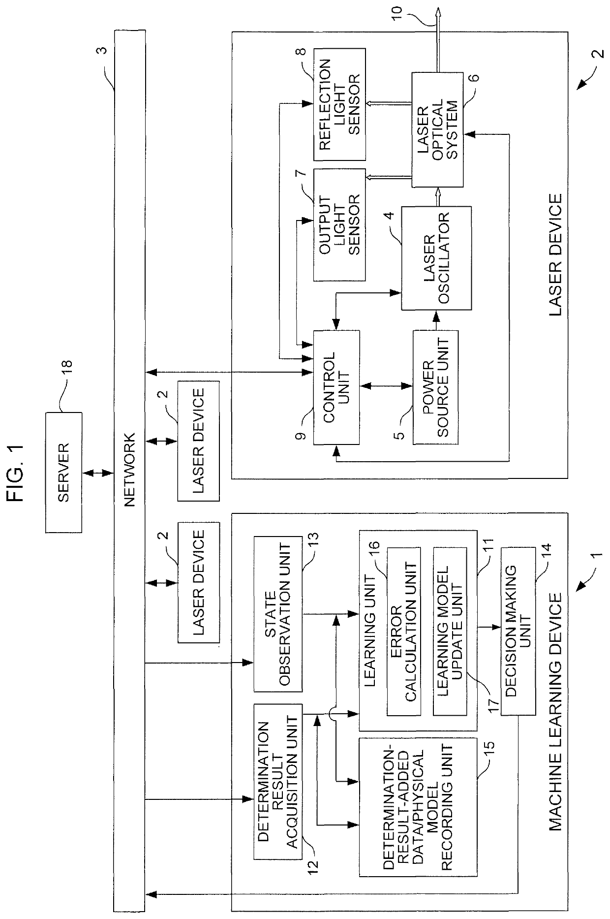
[0072]FIG. 1 is a block diagram illustrating the conceptual configuration of a machine learning device 1 according to a first embodiment of the present invention and illustrating a state in which the machine learning device 1 is connected with three laser devices 2 via a network 3. The laser device 2 positioned right end among the three laser devices 2 is illustrated in a block diagram which illustrates the conceptual configuration of the laser device.

[0073]The laser device 2 includes a laser oscillator 4, a power source unit 5, a laser optical system 6, an output light sensor 7, a reflection light sensor 8, and a control unit 9. The power source unit 5 supplies driving current to the laser oscillator 4. The laser optical system 6 includes a machining head for irradiating a workpiece (not shown) which is a laser machining object with laser light, which is emitted from the laser oscillator 4, through an optical fiber. The output light sensor 7 detects light output of laser light 10 e...

second embodiment

[0117]FIG. 4 is a block diagram illustrating the conceptual configuration of a machine learning device 101 according to a second embodiment of the present invention and illustrating a state in which the machine learning device 101 is connected with three laser devices 2 via the network 3, as is the case with FIG. 1. The laser device 2 positioned right end among the three laser devices 2 is illustrated in a block diagram which illustrates the conceptual configuration of the laser device.

[0118]The configuration of the laser device 2 is the same as that illustrated in FIG. 1 (first embodiment). FIG. 4 is different from FIG. 1 in that FIG. 4 illustrates an example of the machine learning device 101 employing reinforcement learning in the present embodiment and a learning unit 111 includes a reward calculation unit 19 and a value function update unit 20 instead of the error calculation unit 16 and the learning model update unit 17. Further, this machine learning device 101 does not inclu...

third embodiment

[0150]FIGS. 9A and 9B are flowcharts illustrating an example of an operation of a machine learning device according to a third embodiment of the present invention.

[0151]According to an operation of these flowcharts, the machine learning device 1 which performs learning by supervised learning according to the first embodiment of the present invention also has a function as a preventive maintenance device by referring to a quantitative failure occurrence mechanism which corresponds to each failure among various types of failures and which is acquired through the learning, and when a value of any state variable, or a point whose coordinate values are values of a plurality of any state variables, of any laser device 2 which is connected to be mutually communicable via the network 3 comes close to a failure occurrence area, in which a failure occurs by any quantitative failure occurrence mechanism, more than a predetermined range, issuing a command of a failure avoidance driving conditio...


PUM

PropertyMeasurementUnit
currentaaaaaaaaaa
timeaaaaaaaaaa
temperatureaaaaaaaaaa

Abstract

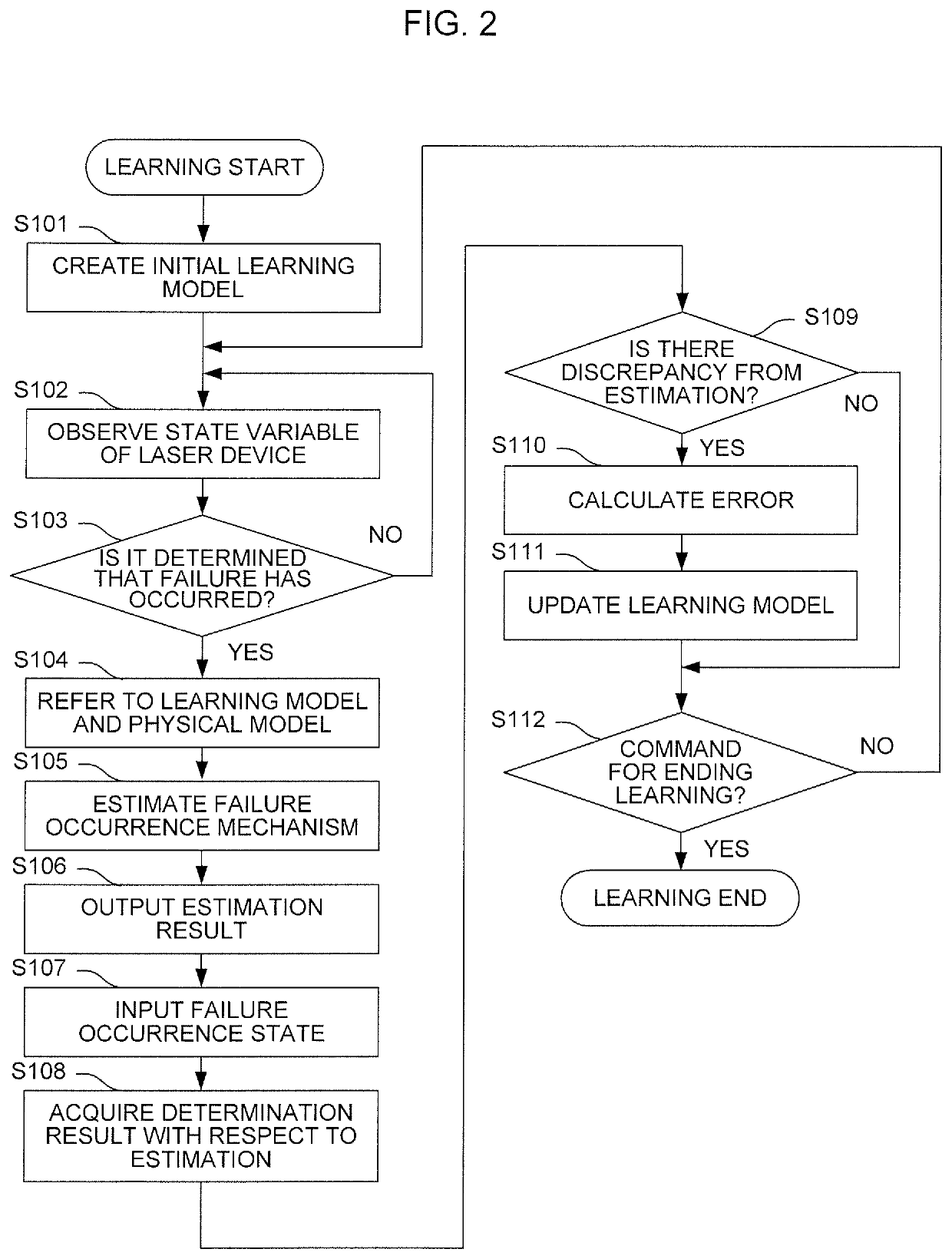
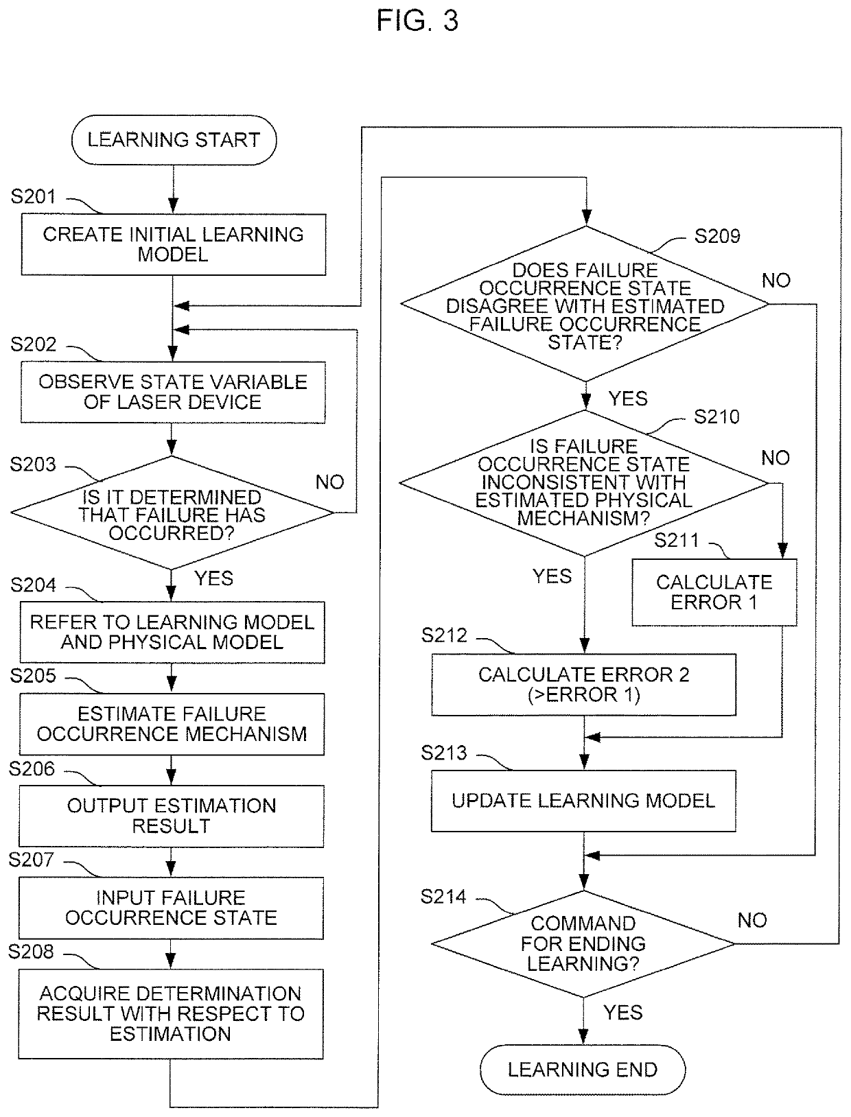
A machine learning device observes a state variable of the inside and the outside of a laser device including time-series data of light output, which is detected by an output light sensor, and a light output command through a control unit of the laser device, and acquires a determination result on correctness with respect to a quantitative failure occurrence mechanism outputted for each failure in the laser device. The machine learning device learns the quantitative failure occurrence mechanism corresponding to each failure while associating the quantitative failure occurrence mechanism with the state variable and the determination result on correctness with respect to the quantitative failure occurrence mechanism, and decides a quantitative failure occurrence mechanism which is to be outputted when an occurrence of each failure is detected.

Description

CROSS-REFERENCE TO RELATED APPLICATION[0001]This application is anew U.S. Patent Application that claims benefit of Japanese Patent Application No. 2018-014132 filed Jan. 30, 2018, the disclosure of this application is being incorporated herein by reference in its entirety for all purposes.BACKGROUND OF THE INVENTION1. Field of the Invention[0002]The present invention relates to a machine learning device that learns quantitative failure occurrence mechanism in a high power laser device. The high power laser device performs laser machining by irradiating a workpiece, from a machining head through an optical fiber, with laser light which is emitted from a laser oscillator using many laser diode modules as light emitting sources or excitation light sources.[0003]More specifically, for failure of a high power laser device that propagates laser light irradiated from a direct diode laser oscillator using many laser diode modules as light emitting sources or a fiber laser oscillator using ...

Claims


Application Information

Patent Timeline
Patent Type & Authority Patents(United States)
IPC IPC(8): G05B23/02G06N20/00H01S5/0683H01S3/00
CPCG05B23/024G05B23/0243G05B23/0281G05B23/0283G06N20/00H01S3/00H01S5/0683G05B2219/33198G05B2219/36199B23K26/50B23K26/705B23Q15/12G06N3/08
Inventor TAKIGAWA, HIROSHITAKAZANE, TETSUHISA
Owner FANUC LTD
Learn More