Power transmission

Inactive Publication Date: 2010-06-10
TAKAI KAZUHIKO +2
View PDF3 Cites 11 Cited by
  • Summary
  • Abstract
  • Description
  • Claims
  • Application Information

AI Technical Summary

Benefits of technology

[0017]Thus, in the power transmission according to the present invention, even in case where there is a torque fluctuation in drive source or drive body side, for example, even if there is an engine fluctuation, its influence can be suppressed as little as possible, occurrence of fatigue of material in the coupling portion is suppr

Problems solved by technology

In the conventional fracture-type torque limiter, however, because fluctuation load due to torque fluctuation entirely acts on the part or the mem

Method used


Image

  • Power transmission
  • Power transmission
  • Power transmission

Examples


Embodiment Construction

[0051]Hereinafter, desirable embodiments of the present invention will be explained referring to figures.

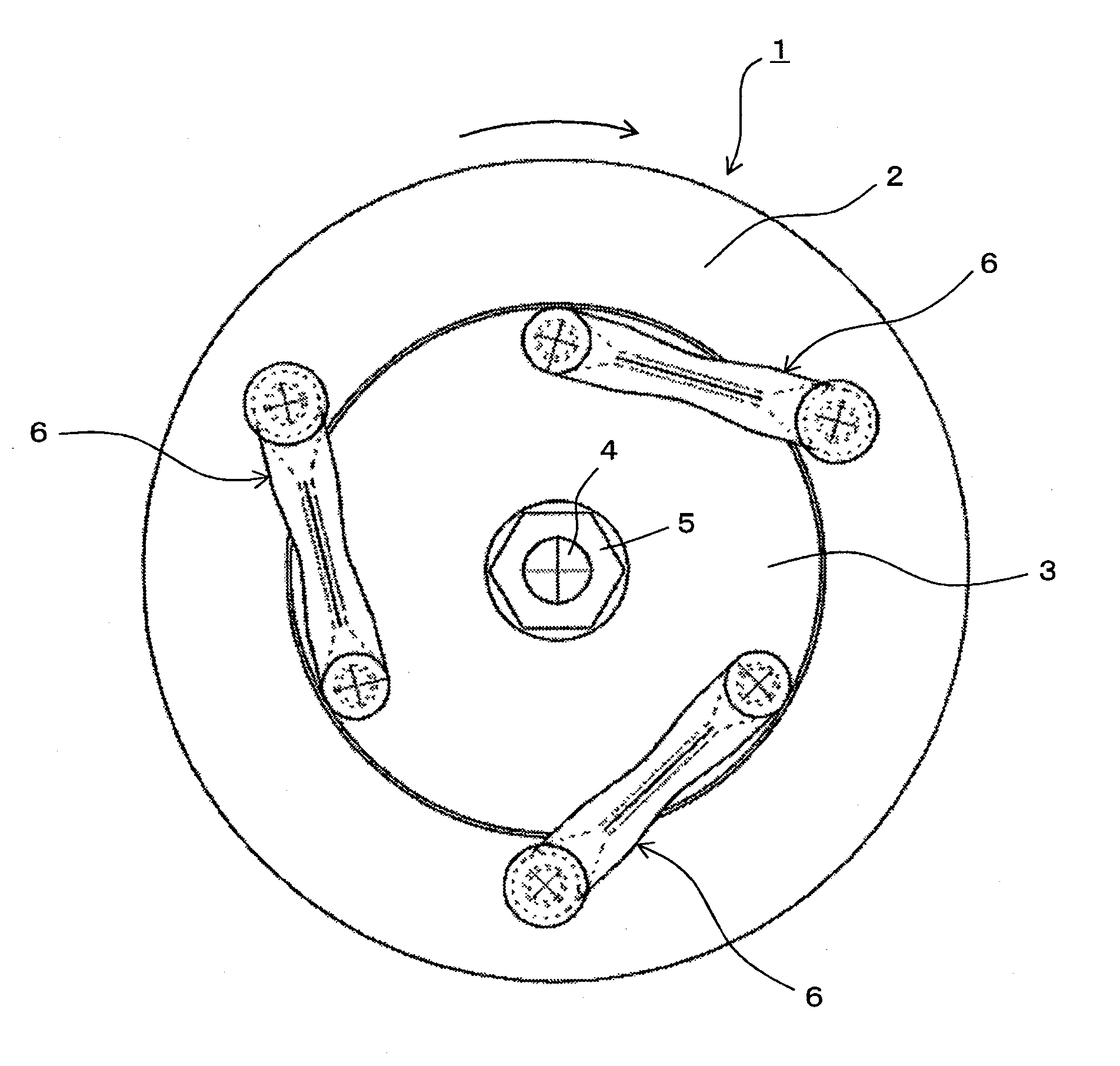
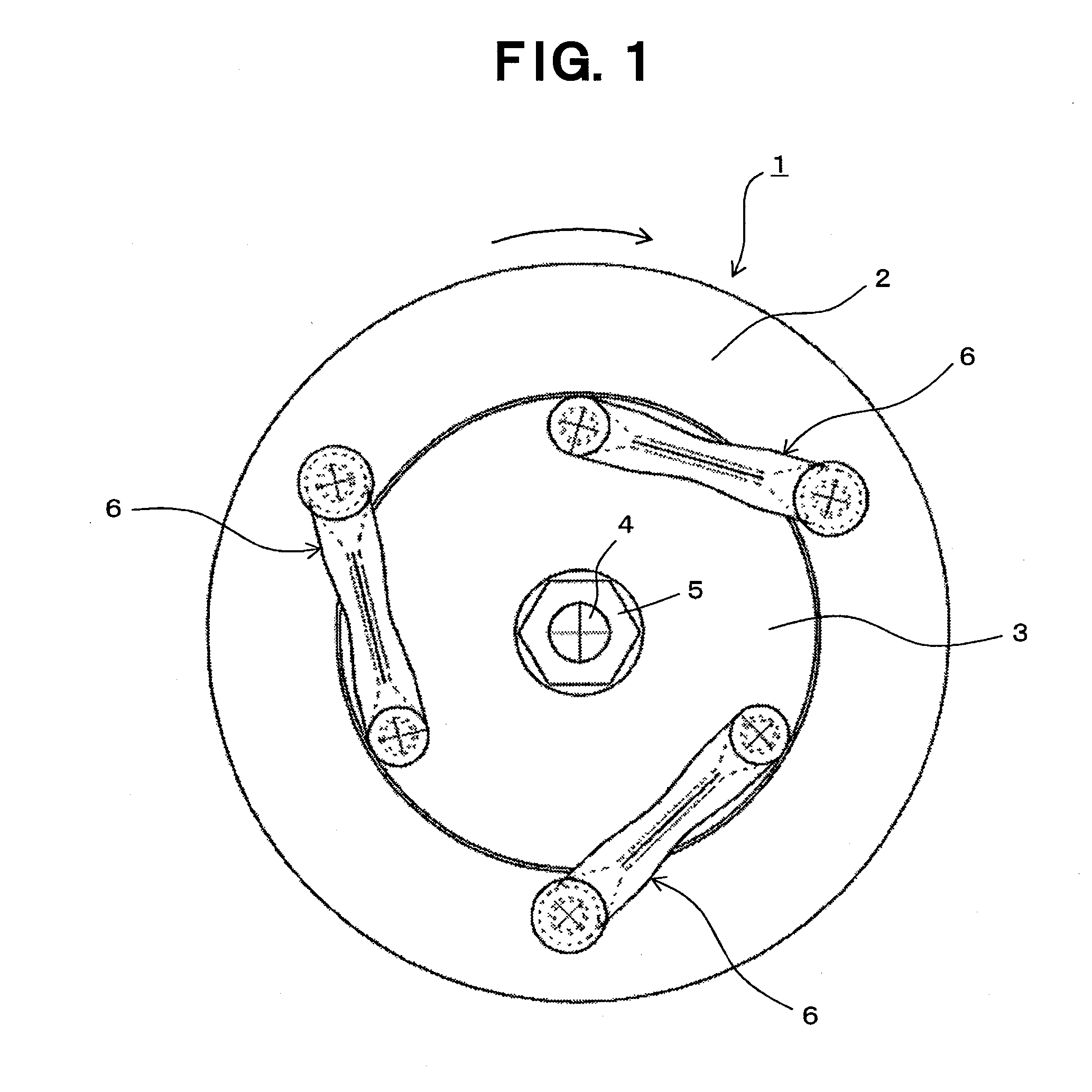
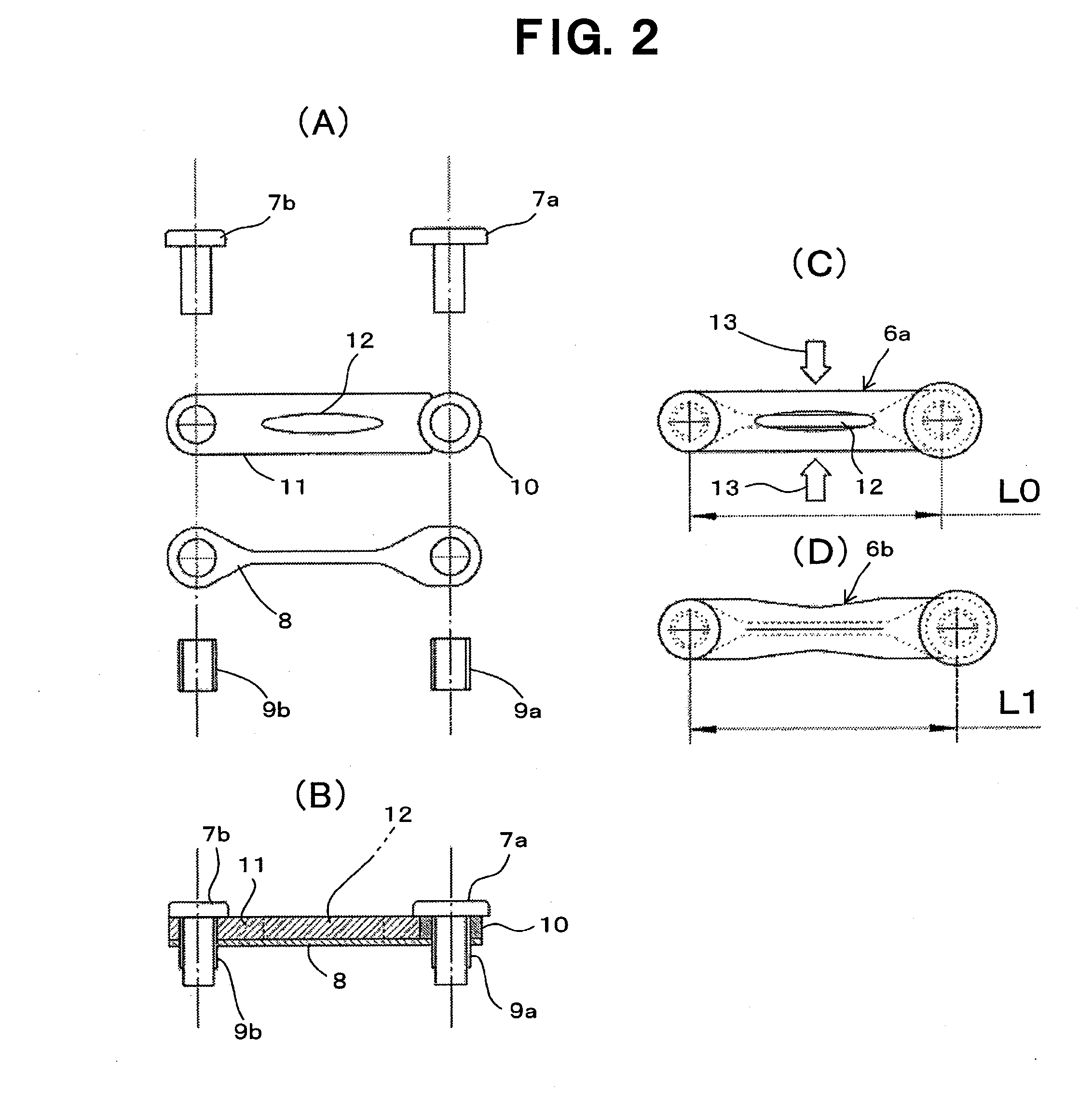
[0052]FIGS. 1 and 2 show a power transmission according to Example 1 of the present invention. In FIG. 1, numeral 1 indicates the entire power transmission, and power transmission 1 has pulley 2 as a drive body, for example, transmitted with a driving force from an engine, and hub 3 as a driven body, for example, connected and fixed to the end portion of main shaft 4 of a compressor via nut 5, which are rotated in the same direction (arrow direction in FIG. 1). These pulley 2 and hub 3 are coupled through coupling portion 6, the torque of pulley 2 provided as a drive body is transmitted to hub 3 provided as a driven body, and when the drive load of the driven body exceeds a predetermined level, the torque transmission is interrupted by fracture of a member (positive torque transmission member) constituting coupling portion 6. In this Example, a plurality of coupling portions 6, i...


PUM


Abstract

A power transmission device having a coupling portion of a driven body and a drive body constituted by combining a positive torque transmission member for transmitting torque in forward rotational direction but interrupting transmission of torque from the drive body by breaking itself when the drive load of the driven body exceeds a predetermined level, with a separate negative torque transmission member for transmitting torque in reverse rotational direction is further provided with a means for generating pretension in the positive torque transmission member in the pulling direction and simultaneously generating a pretension in the negative torque transmission member in the compressing direction after both torque transmission members are combined. A highly reliable power transmission device which can impart a desired pretension precisely and conveniently, and can interrupt torque properly by suppressing fatigue of material at the coupling portion can be provided.

Description

TECHNICAL FIELD OF THE INVENTION[0001]The present invention relates to a power transmission, for example, to a power transmission suitable to transmit driving force from a vehicle engine to a device mounted in the vehicle (e.g. a compressor used in an air conditioning system for the vehicle).BACKGROUND ART OF THE INVENTION[0002]As a conventional technology, a fracture-type torque limiter which has a member or a portion to be fractured when a transmission load over a predetermined value is provided between a member at the driving side and a member at the driven side. For example, in Patent document 1, a fracture-type torque limiter is disclosed wherein, when a compressor is abnormally stopped by a failure, etc., a coupling member which is provided between a pulley at the drive source side and a rotation transmission plate attached to a shaft of the compressor at the driven side is fractured. In the conventional fracture-type torque limiter, however, because fluctuation load due to to...

Claims


Application Information

Patent Timeline
IPC IPC(8): F16D9/04
CPCF16D9/04F16D3/60
Inventor TAKAI, KAZUHIKOHIRAWATARI, SUEJIFUKASAWA, TOSHIKI
Owner TAKAI KAZUHIKO
Why Eureka
Try Eureka