Vibratory Flash Dryer

a flash dryer and vibrating technology, applied in drying machines, lighting and heating equipment, furnaces, etc., can solve the problems of large factory footprint, cage mills subject to clogging, and system not optimal for producing consistent fine particulates

Inactive Publication Date: 2010-06-17
CARRIER VIBRATING EQUIP
View PDF18 Cites 10 Cited by
  • Summary
  • Abstract
  • Description
  • Claims
  • Application Information

AI Technical Summary

Problems solved by technology

These systems are not optimal for producing consistent fine particulates for several reasons.
Firstly, the cage mills are subject to clogging when wet materials are introduced, and thus require several mills for a single process.
Secondly, belt dryers require large material residence time to produce even drying of the material, and thus typically require a large factory footprint.
Fluid beds, either conventional or vibrating, are not optimal for use where the wet material particle sizes are quite small, for example particles sizes less than 50 μm, unless material density is very high.
However, flash dryers do not work particularly well for particulates that are very wet, or enter the process in the form of filter cakes.
These particulates must usually be processed by a mill or screen of some variety, prior to entry into the flash dryer, which adds complexity and expense to the system.
Accordingly, it is readily seen that materials having high moisture content or widely varying particle sizes are difficult to dry and process utilizing existing drying systems.

Method used


Image

  • Vibratory Flash Dryer
  • Vibratory Flash Dryer
  • Vibratory Flash Dryer

Examples


Embodiment Construction

)

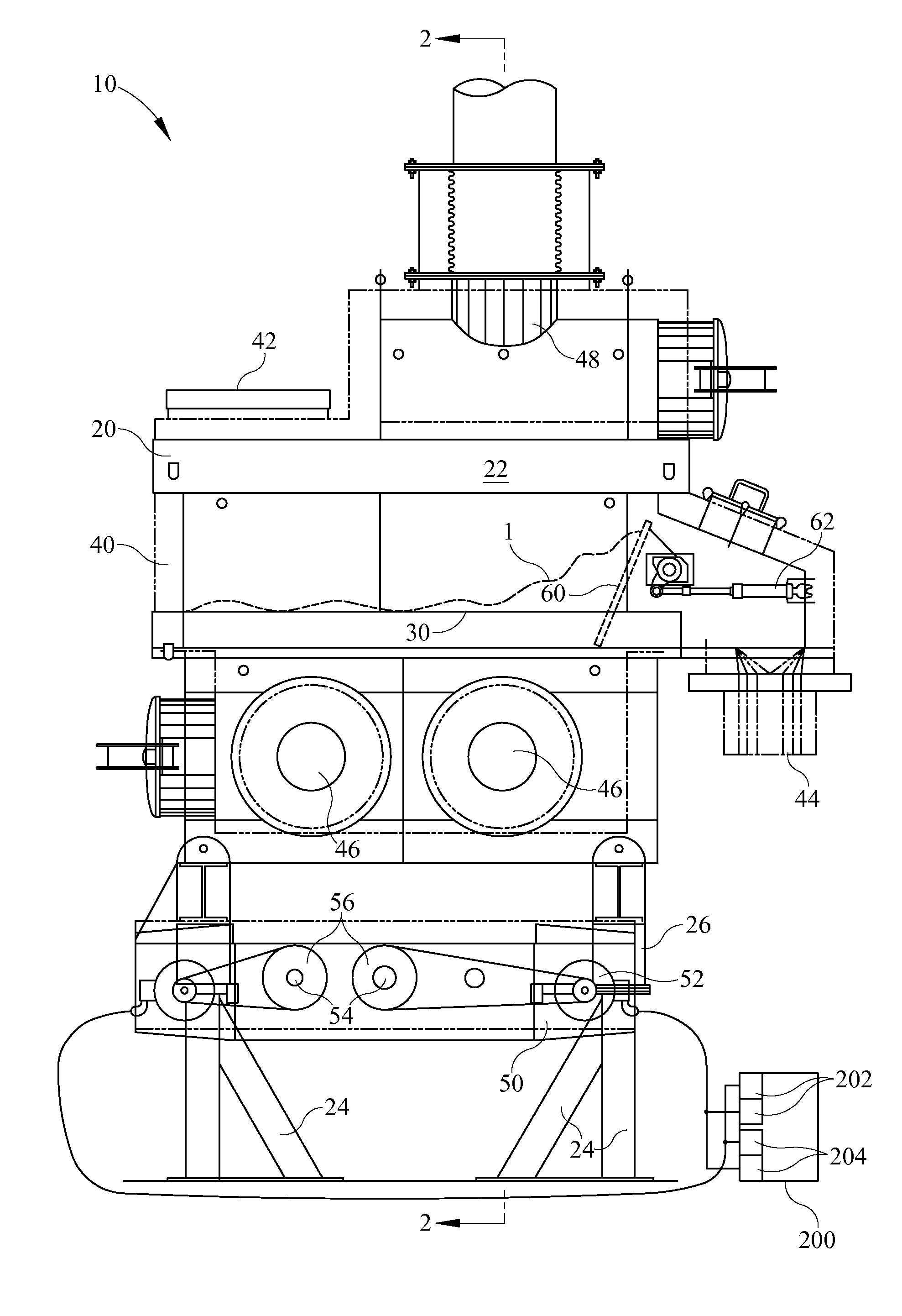
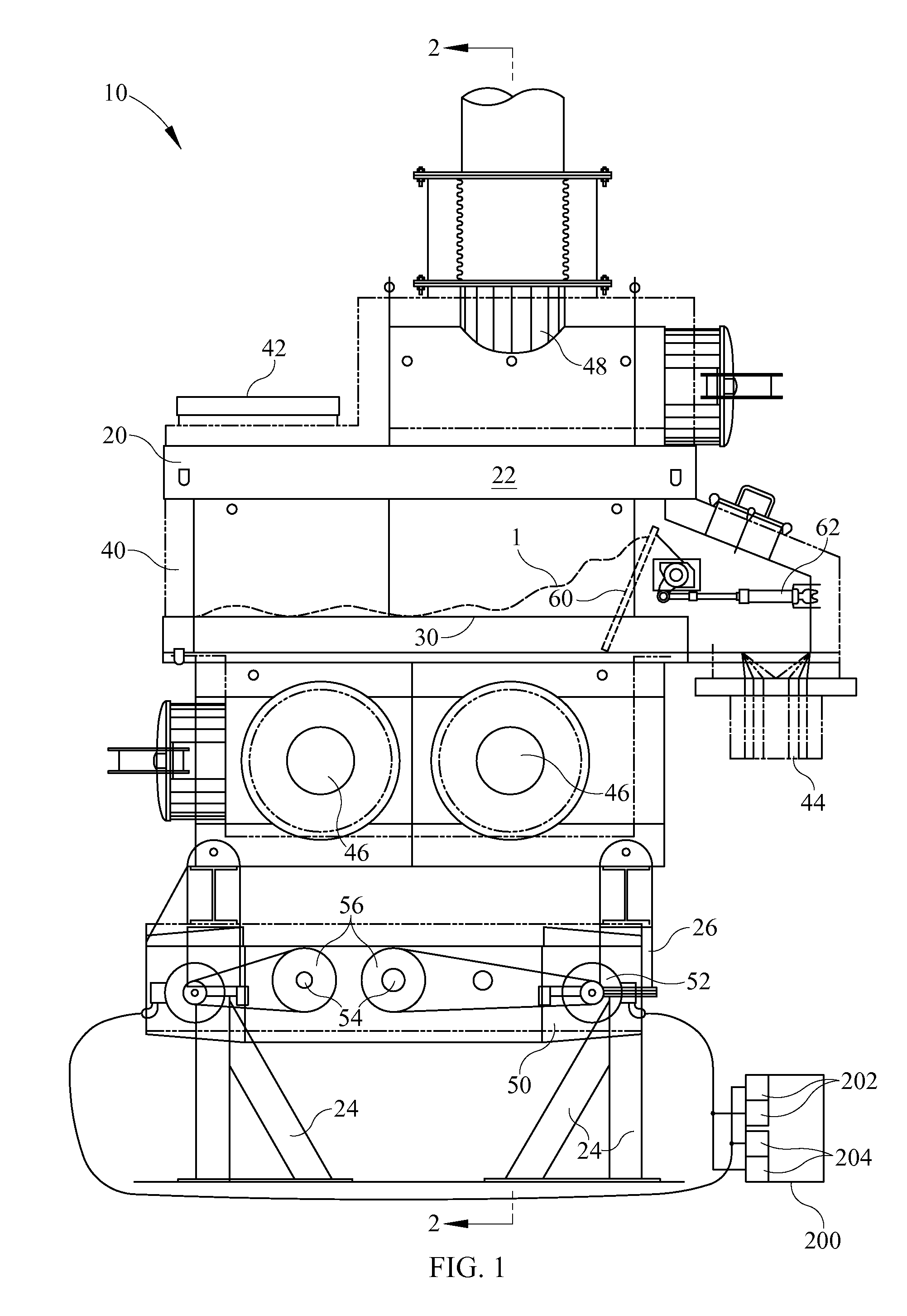
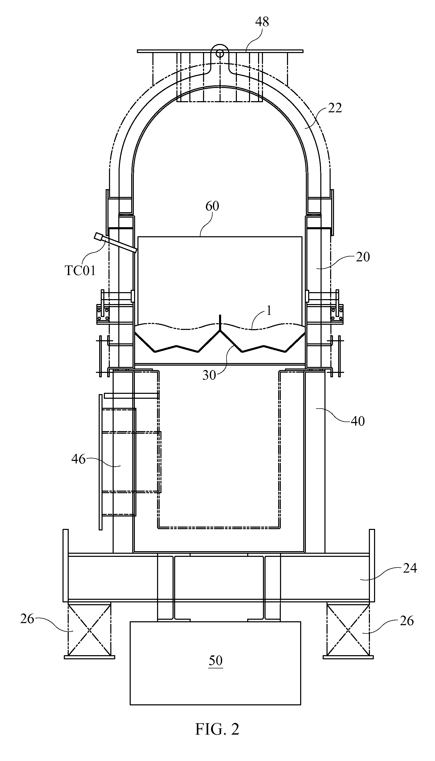
[0020]Referring now to the drawing Figures, and in accordance with a one embodiment of the present invention a vibratory flash dryer system 10 capable of effecting heat transfer to or from a moisture-laden bulk material 1 includes a fluid bed dryer 20 in fluid communication with a flash dryer system 100, each supplied with a hot gas (for example air) by a gas heater system 120. As best seen in FIGS. 1-3, fluid bed dryer 20 comprises an exterior housing 40 mounted to a vibratory frame 24 having spring members 26 for isolating vibration from fluid bed dryer 20. Spring member 26 may be rubber marshmallow type spring or coil springs.

[0021]Fluid bed dryer 20 further includes a distribution plate 30 running longitudinally substantially the length of the housing on which wet or moisture-laden material 1 is deposited, the distribution plate 30 having a plurality of perforations or apertures therein through which hot or cool gas may flow. As shown in the drawing Figures, air flow direction ...


PUM


Abstract

An apparatus for drying and conveying a material includes a vibratory fluid bed dryer having a perforated drying deck on which material is deposited, said fluid bed dryer including a vibratory drive system capable of imparting a variable angle vibratory force to the deck. A flash dryer is also provided, having a fan and heater for supplying hot air through the fluid bed dryer deck and a cyclone for collecting finished, dried material particles.

Description

BACKGROUND OF THE INVENTION[0001]1. Field of the Invention[0002]The present invention relates generally to a system for transporting and drying a moisture laden bulk material and more particularly to a vibratory flash drying system having a fluid bed dryer for effecting rapid heat transfer to moisture laden bulk material operating in conjunction with a flash dryer wherein dried material particles are entrained in an airstream to exit the fluid bed dryer and enter the flash dryer for final processing. Oversized particles are too heavy to be conveyed in the exhaust air stream and thus remain on the fluid bed dryer deck to be either broken up with vibratory motion or discharged from a discharge end of the fluid bed dryer.[0003]2. Description of the Related Art[0004]Various types of systems for heating and drying various filter cakes and like products that are typically processed into fine powders are known in the art. Many manufacturing industries produce particles, powders, or granule...

Claims


Application Information

Patent Timeline
Patent Type & Authority Applications(United States)
IPC IPC(8): F26B17/00F26B19/00
CPCF26B3/0923F26B3/0926F26B17/10F26B21/10
Inventor BAKER, STEPHEN T.HUBBS, DAVID
Owner CARRIER VIBRATING EQUIP
Why Eureka
Try Eureka