Method of determining end member concentrations

Inactive Publication Date: 2010-06-17
SCHLUMBERGER TECH CORP
View PDF4 Cites 34 Cited by
  • Summary
  • Abstract
  • Description
  • Claims
  • Application Information

AI Technical Summary

Benefits of technology

[0016]With a sufficient number of changes of the relative flow rates and/or a sufficient number of geomarkers used in the method, the system of mass balance equations can be solved even when the number of different sources or layers is an unknown. However, a solution of the system becomes easier and more accurate when the number of contributing sources is known. An even more preferred case for applying the novel method involves the step of measuring the flow rates of each contributing source or layer, thus eliminating the flow rates as unknowns through direct measurement. The flow rates of i...

Problems solved by technology

But it can also be caused by a successive opening or temporary blo...

Method used


Image

  • Method of determining end member concentrations
  • Method of determining end member concentrations
  • Method of determining end member concentrations

Examples


Embodiment Construction

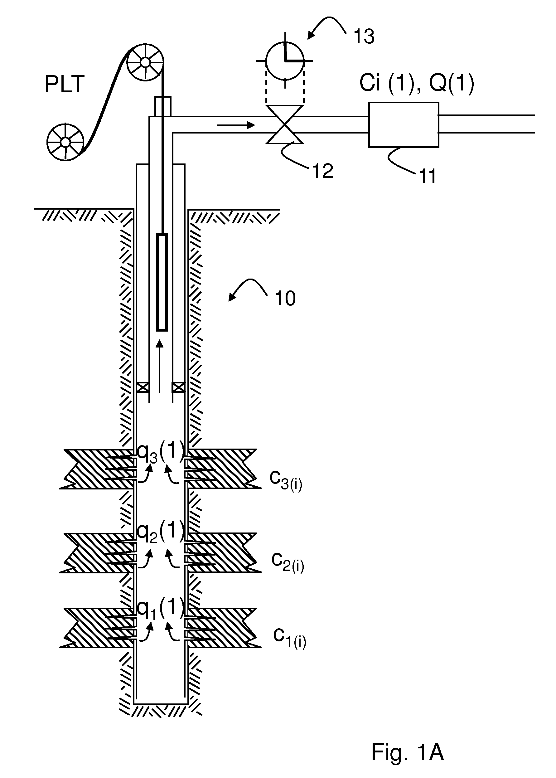
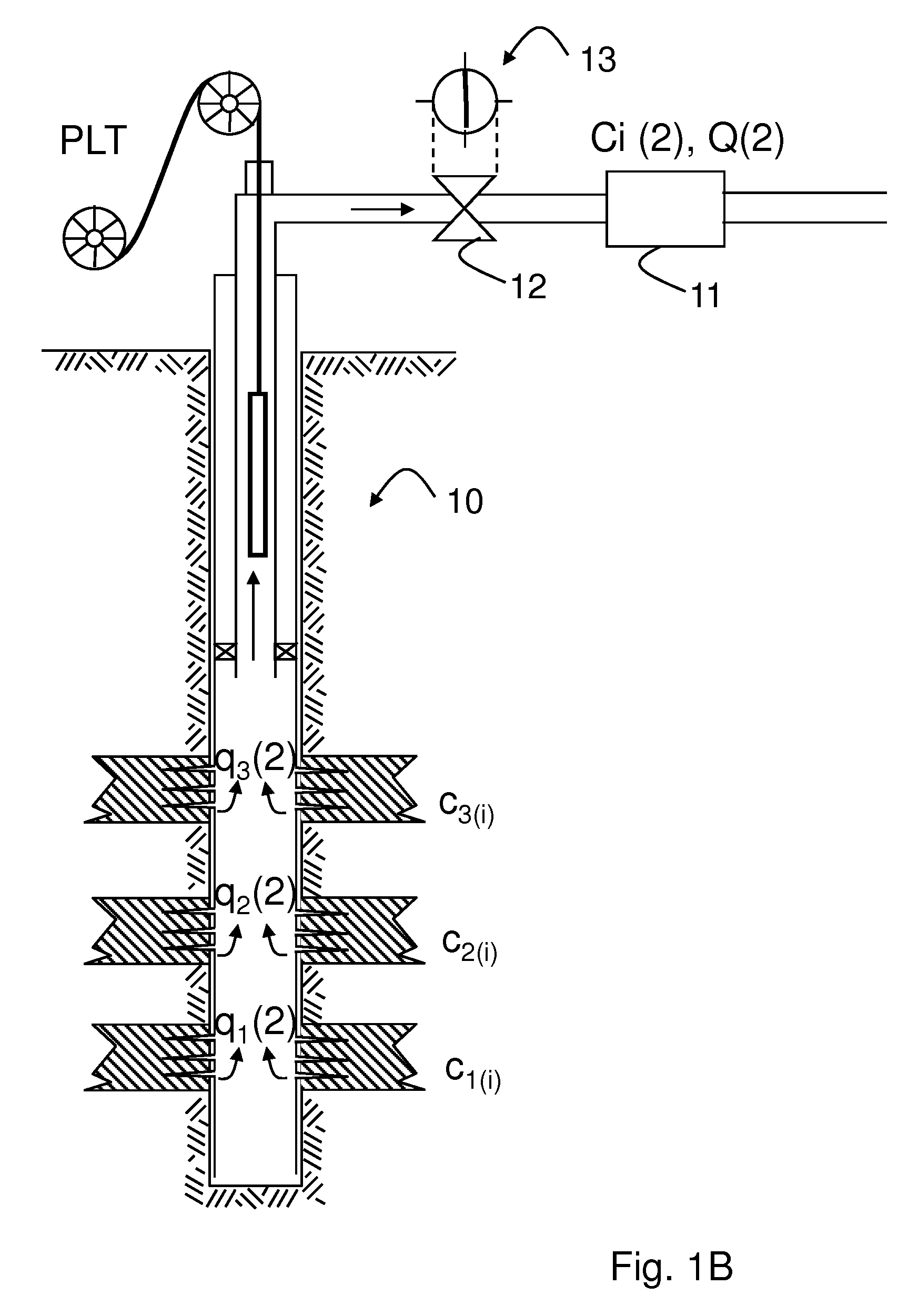
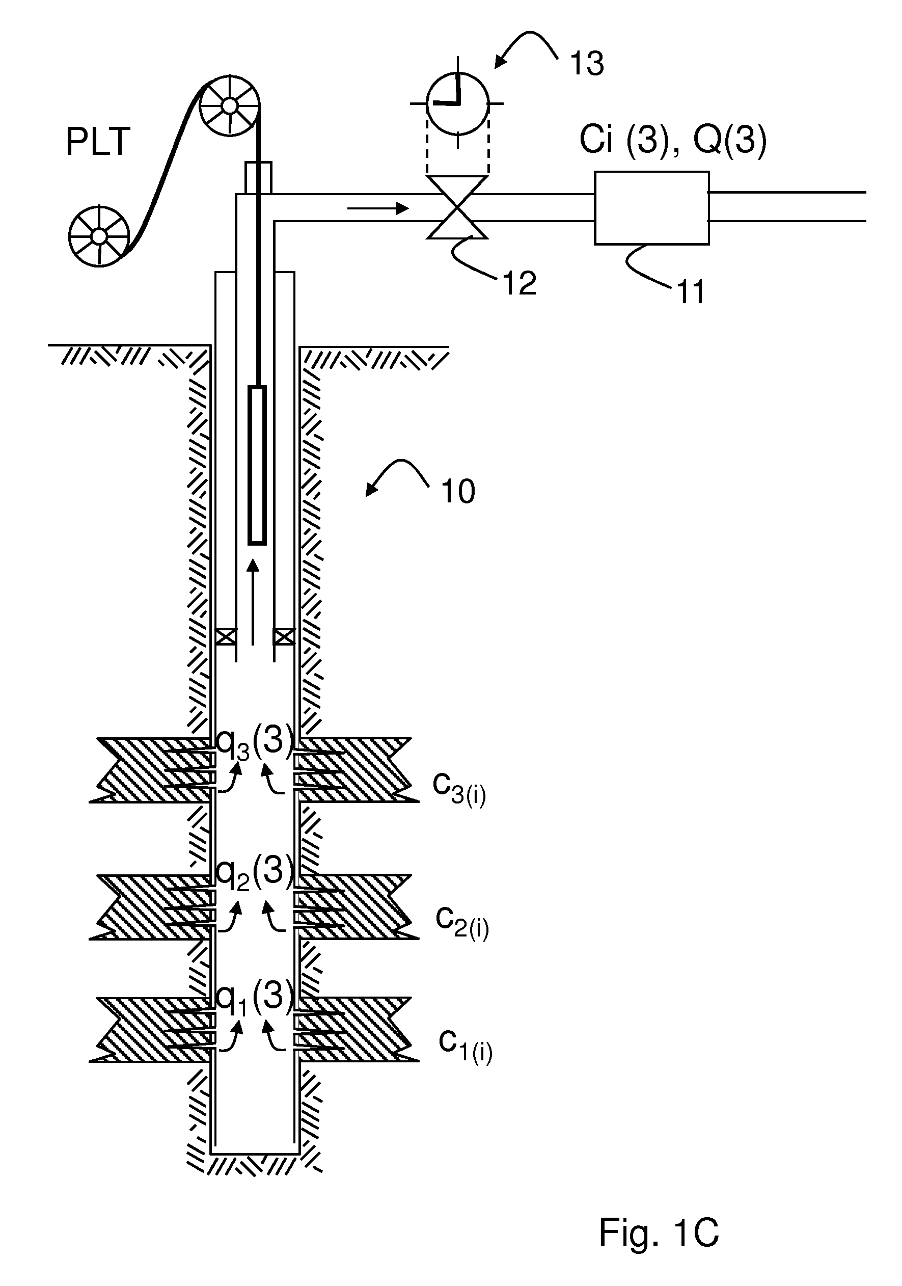
[0022]The method is illustrated by the following example, in which FIGS. 1A-1C shows an oil well 10 drilled in a formation containing several oil-bearing layers. In this example, the number of separate layers is chosen to be three to allow for a clearer description of elements of the present invention. However, the number of layers can vary and the below described example is independent of any specific number of layers.

[0023]In the example, there is assigned to each layer a flow rate q1, q2, and q3, respectively. The fluids produced of the three layers contain chemical components at concentrations c1i, c2i and c3i, respectively, wherein the index number i denotes a specific component i in the fluid.

[0024]In the present example, the component i stands for any component selected as geomarker for later application of a back allocation through fingerprinting. It will be apparent from the following description that the method can be applied to any number of such components or geomarkers ...


PUM


Abstract

A method of determining a concentration of a component in a flow from a single source or layer contributing to a total flow is described using the steps of repeatedly changing the relative flows from the source; and for each of the changed relative flows determining the combined flow rate and a total concentration of the component of the total flow until sufficient data points are collected to solving a system of mass balance equations representing the flow of the component from each source at each of the changed flow rates.

Description

FIELD OF THE INVENTION[0001]The invention relates to methods of determining the number of distinct subterranean sources or zones contributing to a total production flow and / or allocating the relative contributions of two or more distinct sources in a well or several wells to the total flow based on compositional analysis or compositional fingerprinting.BACKGROUND[0002]In hydrocarbon exploration and production there is a need to determine the approximate composition of oil samples in order to investigate their origin and properties. The production systems of developed hydrocarbon reservoirs typically include pipelines which combine the flow of several sources. These sources can be for example several wells or several producing zones or reservoir layers within a single well. It is a challenge in the oilfield industry to back allocate the contributions of each source from a downstream point of measurement at which the flow is already commingled.[0003]Other than for back allocation, com...

Claims


Application Information

Patent Timeline
IPC IPC(8): G01F1/00
CPCE21B47/10G01F15/063G01F1/74E21B47/1015E21B47/11
Inventor ZIAUDDIN, MURTAZA
Owner SCHLUMBERGER TECH CORP
Why Eureka
Try Eureka