
Security mechanism for a flow control device on a railcar and method of coupling the same

a technology of flow control device and security mechanism, which is applied in the direction of valve operating device/release device, mechanical apparatus, manufacturing tools, etc., can solve the problems of sealing having to be removed or irreparably damaged

Inactive Publication Date: 2010-06-17
AMERICAN RAILCAR IND
View PDF53 Cites 2 Cited by
  • Summary
  • Abstract
  • Description
  • Claims
  • Application Information

AI Technical Summary

Benefits of technology

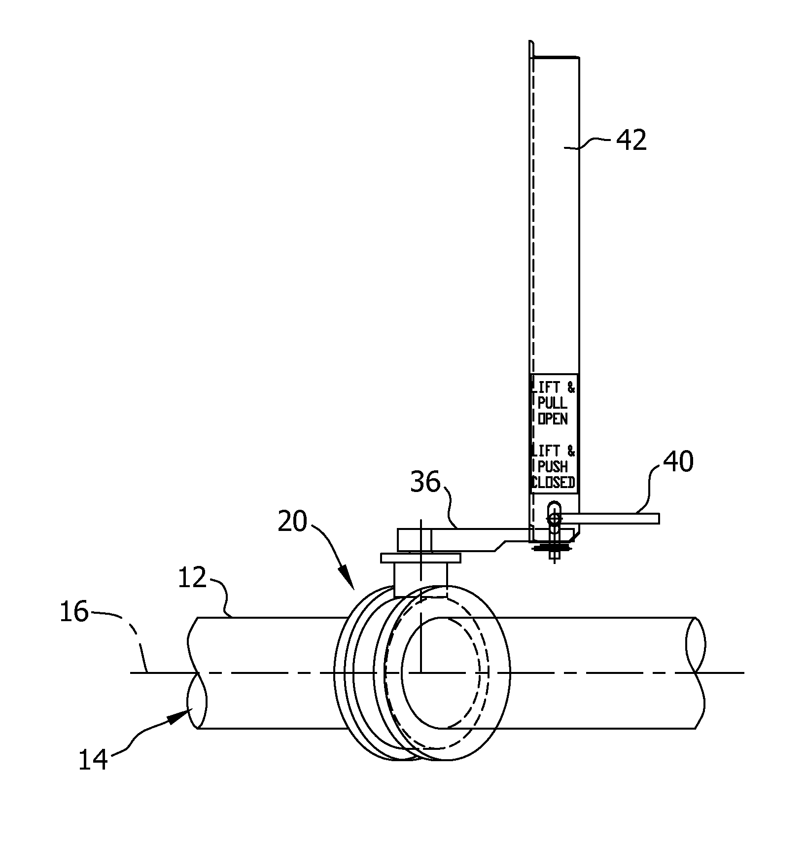
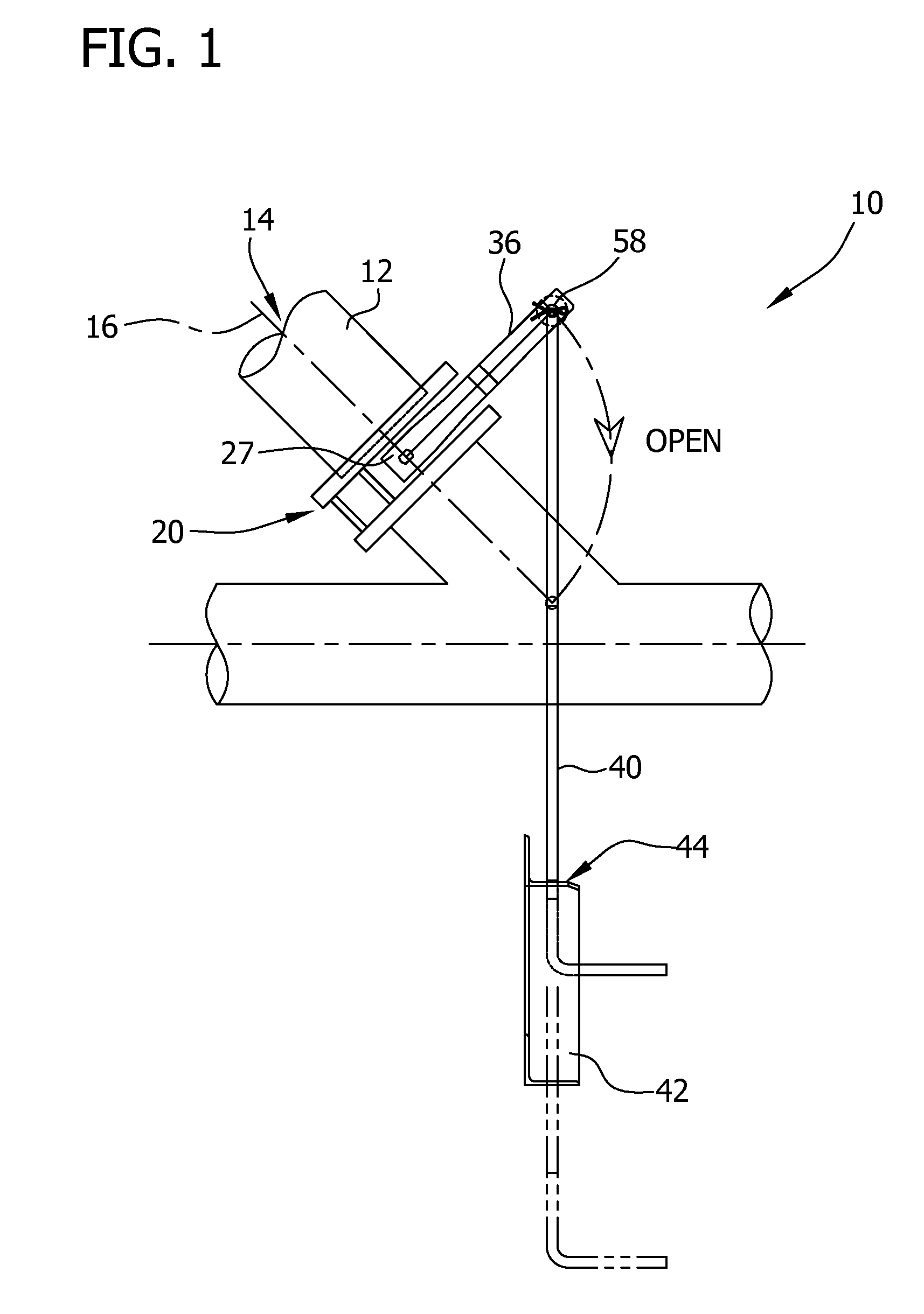
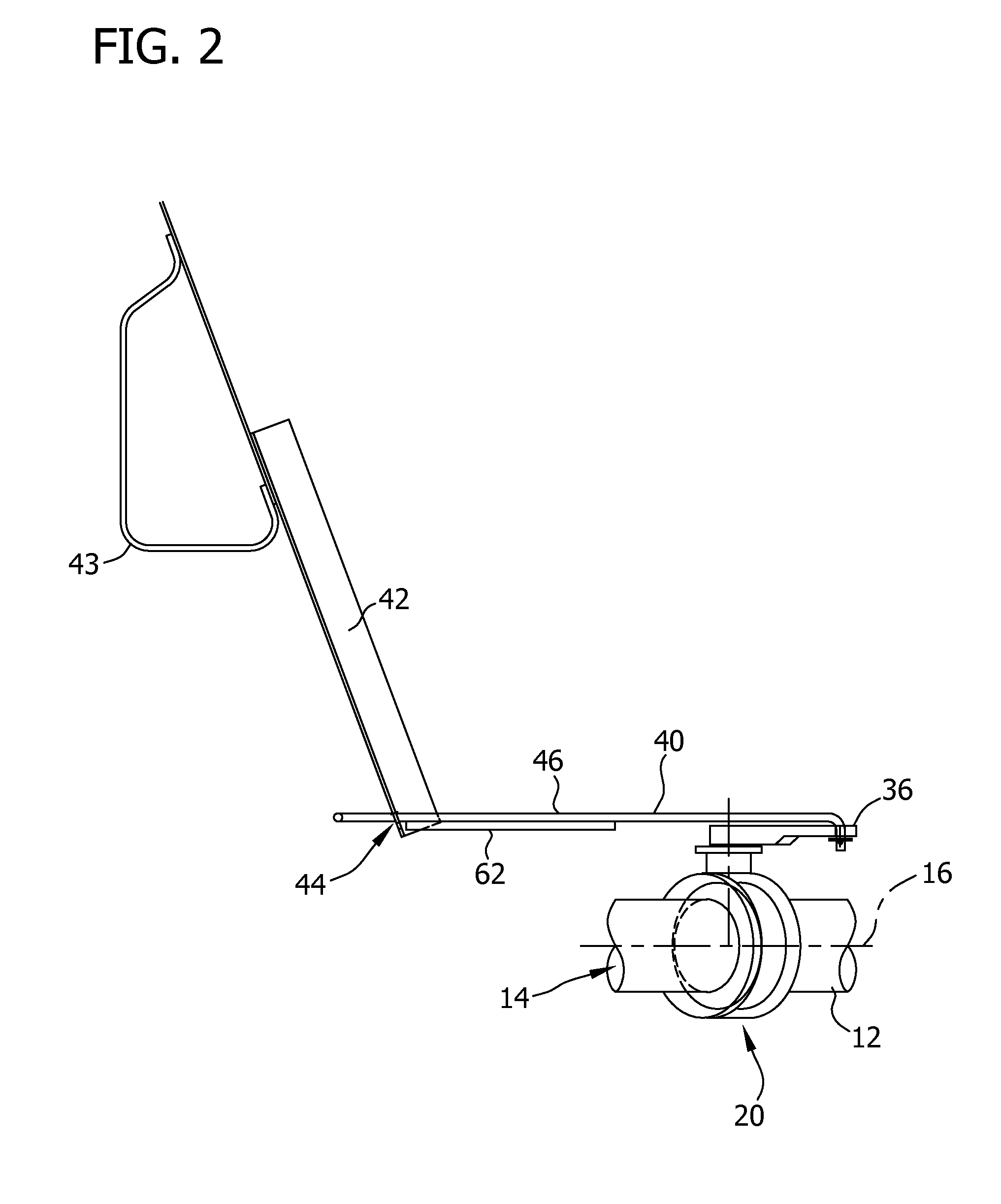
The patent describes a security mechanism for a flow control device on a railcar. The mechanism includes a support member and an extension handle that is slidably coupled to the support member. The extension handle has a first end that is connected to the flow control device and a second end that forms a handle member. A securement member is used to prohibit movement of the handle member relative to the support member. The securement member is connected to the handle member at the second end. The technical effect of this mechanism is to provide a secure and effective way to control the flow of fluid on a railcar.

Problems solved by technology

These security seals must be either removed or irreparably damaged in order to open the flow control valves.
Unfortunately, with respect to these known railcars, the network of transfer lines or pipes, and flow control valves and corresponding security seals are disposed beneath the railcar and are coupled to the underside of the railcar such that an operator of the railcar must maneuver beneath the railcar to manually apply and / or remove the security seal to open one or more of the flow control valves to release the material from within the hopper.

Method used


Image

  • Security mechanism for a flow control device on a railcar and method of coupling the same
  • Security mechanism for a flow control device on a railcar and method of coupling the same
  • Security mechanism for a flow control device on a railcar and method of coupling the same

Examples


Embodiment Construction

[0026]The present disclosure describes a valve system including a flow control device operatively coupled to a pipe in material flow communication with a hopper of a railcar. More specifically, the pipe defines a passage in material flow communication with a volume defined within the railcar hopper. The material is moved through the pipe passage to transfer the material from within the hopper into a suitable container for further transport and / or storage. The material transported within the railcar hopper includes powdered, granular or liquid material. An extension handle is operatively coupled to the flow control device to operate or control the flow control device. The extension handle extends laterally outward from the underside of the railcar and through a support member coupled to a side sill of the railcar to allow an operator to open and close a valve of the flow control device while standing next to the railcar and without having to crawl and / or reach under the railcar. Furt...


PUM

PropertyMeasurementUnit
flexibleaaaaaaaaaa
shapeaaaaaaaaaa
internal volumeaaaaaaaaaa

Abstract

A security mechanism for a flow control device on a railcar and method of coupling the security mechanism to the flow control device are provided. A support member is coupled to the railcar. An extension handle has a first end operatively coupled to the flow control device on the railcar. An opposing second end of the extension handle forms a handle member. The extension handle is slidably coupled to the support member. A securement member is provided for coupling the support member to the extension handle to prohibit movement of the extension handle relative to the support member. The securement member is coupled to the extension handle proximate to the second end.

Description

CROSS REFERENCE TO RELATED APPLICATIONS[0001]This application is a continuation-in-part of U.S. patent application Ser. No. 12 / 170,052, filed Jul. 9, 2008, entitled “A Valve Extension Handle and Method of Using The Same,” which is hereby incorporated by reference in its entirety.BACKGROUND OF THE INVENTION[0002]The field of the disclosure relates generally to flow control valves and, more particularly, to a securement member to limit movement of an extension handle for operating a flow control valve positioned on an underside of a railcar.[0003]Railcars have long been used to store and transport liquid, powdered and granular materials. These railcars may be cylindrical or rectangular in shape and include one or more enclosed hoppers that facilitate securely and efficiently transporting the materials to a destination while minimizing material loss during transport.[0004]In at least some known railcars, the materials contained within the railcars are discharged from the railcar using ...

Claims


Application Information

Patent Timeline
Patent Type & Authority Applications(United States)
IPC IPC(8): F16K31/00B23P11/00
CPCB25G1/04Y10T29/49826F16K31/602F16K1/221
Inventor RECKKER, CHRISTOPHEROHMES, GERALD W.
Owner AMERICAN RAILCAR IND
Learn More