Stacked Die Parallel Plate Capacitor

a parallel plate capacitor and die-cutting technology, applied in the field of integrated circuits, can solve the problems of increasing the number of transistors that are included in the integrated circuit, the conflict between the number of transistors in the integrated circuit and the size of the integrated circuit, and the complexity of the circui

Inactive Publication Date: 2010-06-17
QUALCOMM INC
View PDF31 Cites 146 Cited by
  • Summary
  • Abstract
  • Description
  • Claims
  • Application Information

AI Technical Summary

Problems solved by technology

As circuits increase in complexity, the number of transistors that are included in integrated circuits has increased.
As complexity has increased, demand for smaller and more portable electronics has resulted in a conflict between the number of transistors in the integrated circuit and the size of the integrated circuit.
However, building multiple layers of semiconductor dies could increase the density of transistors several fold.
One challenge to designing integrated circuits is the placement of passive components around transistors in an efficient manner.
Still, there are areas of the die that are not used for active circuitry that could otherwise be used for passive structures.
These methods all consume area on the die.
Although offering a small footprint, the MIM capacitor still consumes area that otherwise could be used for active circuitry.

Method used


Image

  • Stacked Die Parallel Plate Capacitor
  • Stacked Die Parallel Plate Capacitor
  • Stacked Die Parallel Plate Capacitor

Examples


Embodiment Construction

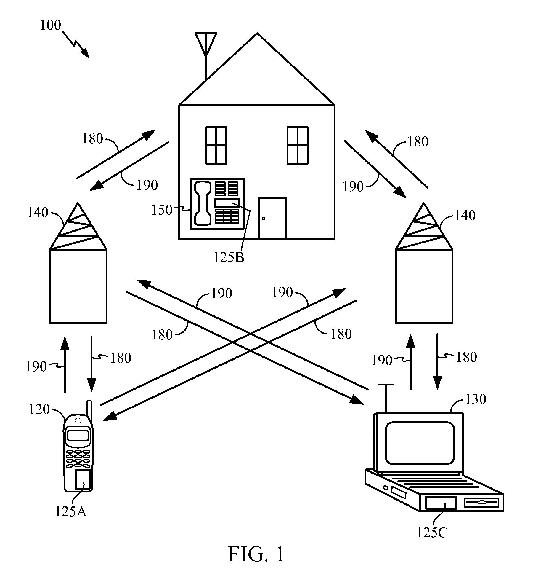
[0016]FIG. 1 is a block diagram showing an exemplary wireless communication system 100 in which an embodiment of the disclosure may be advantageously employed. For purposes of illustration, FIG. 1 shows three remote units 120, 130, and 150 and two base stations 140. It will be recognized that typical wireless communication systems may have many more remote units and base stations. Remote units 120, 130, and 150 include IC devices 125A, 125B and 125C, that include the circuitry disclosed here. It will be recognized that any device containing an IC may also include the circuitry disclosed here, including the base stations, switching devices, and network equipment. FIG. 1 shows forward link signals 180 from the base stations 140 to the remote units 120, 130, and 150 and reverse link signals 190 from the remote units 120, 130, and 150 to base stations 140.

[0017]In FIG. 1, remote unit 120 is shown as a mobile telephone, remote unit 130 is shown as a portable computer, and remote unit 150...


PUM


Abstract

A stacked integrated circuit having a first die with a first surface and a second die with a second surface facing the first surface, the stacked integrated circuit includes a capacitor. The capacitor is formed by a first conducting plate on a region of the first surface, a second conducting plate on a region of the second surface substantially aligned with the first conducting plate, and a dielectric between the first conducting electrode and the second conducting electrode.

Description

TECHNICAL FIELD[0001]The present disclosure generally relates to integrated circuits (ICs). More specifically, the present disclosure relates to stacked ICs, and even more specifically to capacitors used in stacked ICs.BACKGROUND[0002]Integrated circuits (ICs) are fabricated on substrates. Commonly, these substrates are semiconductor materials, and, in particular, silicon. As circuits increase in complexity, the number of transistors that are included in integrated circuits has increased. As complexity has increased, demand for smaller and more portable electronics has resulted in a conflict between the number of transistors in the integrated circuit and the size of the integrated circuit.[0003]Transistor sizes have shrunk from, most recently, 65 nm to 45 nm, and will soon reach 32 nm. This reduction results in an increased density of the number of transistors in each unit of square area. Increasing transistor densities has allowed integrated circuits to continue to increase in comp...

Claims


Application Information

Patent Timeline
Patent Type & Authority Applications(United States)
IPC IPC(8): H01L23/48
CPCH01L23/50H01L23/642H01L25/0657H01L2224/16225H01L2225/06517H01L2225/06527H01L2225/06541H01L2225/06513H01L2224/05573H01L2224/13025H01L2924/00014H01L2224/0554H01L2224/05599H01L2224/0555H01L2224/0556
Inventor CHANDRASEKARAN, ARVIND
Owner QUALCOMM INC
Why Eureka
Try Eureka