
Imaging Device

Active Publication Date: 2010-06-17
KEYENCE
View PDF18 Cites 15 Cited by
  • Summary
  • Abstract
  • Description
  • Claims
  • Application Information

AI Technical Summary

Benefits of technology

[0008]The present invention has been made in view of the above circumstances, and an object of the present invention is to provide an imaging device capable of easily recognizing a positional relationship between a field of view during photographing and a mosaic image during creation. More particularly, another object of the present invention is to provide an imaging device capable of displaying the whole of a display mosaic image in a screen even when the image size of the mosaic image is largely changed before and after the assembly in the case of fetching a still image and assembling the same to the mosaic image while displaying the field of view during photographing as a moving picture image at an appropriate position on the mosaic image.
[0010]In the imaging device, the field of view during photographing is displayed as the moving picture image made of the display frame images at an appropriate position on the display mosaic image, and the still images photographed by the camera are fetched and assembled on the mosaic image; and accordingly, a new mosaic image is generated. Then, when the frame image and the mosaic image are reduced respectively to generate the display frame image and the display mosaic image, reduction in image is performed based on the image size of the mosaic image. According to such a configuration, the reduction in image is performed based on the image size of the mosaic image; and therefore, even when the image size of the mosaic image is largely changed before and after the assembly, the whole of the display mosaic image can be displayed in a screen. Therefore, a positional relationship between the field of view during photographing and the mosaic image during creation can be easily recognized.
[0011]In the imaging device of a second aspect of the present invention, in addition to the above configuration, the display reduction unit reduces the frame image and the mosaic image so that the whole of the display mosaic image is displayed in a screen. According to such a configuration, in the case of displaying the moving picture image made of the display frame images on the display mosaic image as a live image, the whole of the mosaic image is always displayed in the screen, and therefore, a user can easily recognize that a positional relationship between the field of view during photographing and the mosaic image during creation.
[0012]According to such a configuration, in the case of displaying the moving picture image made of the display frame images as the live image on the display mosaic image, the whole of the mosaic image and the whole of the frame image are always displayed at the same time; and therefore, a user can easily recognize that a positional relationship between the field of view during photographing and the mosaic image during creation.
[0014]In the imaging device of a fifth aspect of the present invention, in addition to the above configuration, the display reduction unit updates a reduction ratio in the case of reducing the frame image and the mosaic image each time the display position of the display frame image with respect to the display mosaic image is updated. According to such a configuration, the reduction ratio in the case of reducing the frame image and the mosaic image is updated each time the display position of the display frame image is updated; and therefore, the whole of the display mosaic image and the display frame image can be appropriately displayed in a screen by following the update of the display position.
[0016]The imaging device of an eighth aspect of the present invention, in addition to the above configuration, further includes: a positioning reduction section which reduces the frame image and the mosaic image at a constant reduction ratio respectively, and generates a positioning frame image and a positioning mosaic image; and a feature quantity extraction unit which extracts feature quantity from the positioning frame image and the positioning mosaic image, wherein the relative position determination unit determines a relative position between the positioning frame image and the positioning mosaic image by comparison of the feature quantity; and wherein the display reduction unit reduces the frame image and the mosaic image so that the whole of the display mosaic image and the whole of the display frame image, a part of the display frame image overlapping with the positioning mosaic image, and corresponding to the positioning frame image at any position that has an overlap area necessary for determination of the relative position are displayed in a screen. According to such a configuration, by comparison of the feature quantity extracted from the positioning frame image and the positioning mosaic image, the relative position between these images is determined; and therefore, it becomes possible to suppress system configuration from being complicated.

Problems solved by technology

Furthermore, the position of the movable stage needs to be highly accurately detected; and therefore, there is a problem in that system configuration becomes complicated and high cost.
However, there is not an imaging device capable of fetching still images and coupling the same with a mosaic image while making a user confirm a positional relationship between a field of view during photographing and the mosaic image during creation on a display unit.
In such imaging device, the image size of the mosaic image varies by the assembly; and therefore, there is a problem in that a part of the mosaic image is not displayed on a screen and a positional relationship between the field of view during photographing and the mosaic image during creation becomes unclear.

Method used


Image

  • Imaging Device
  • Imaging Device
  • Imaging Device

Examples


embodiment 1

Preferred Embodiment 1

Magnification Observation Device

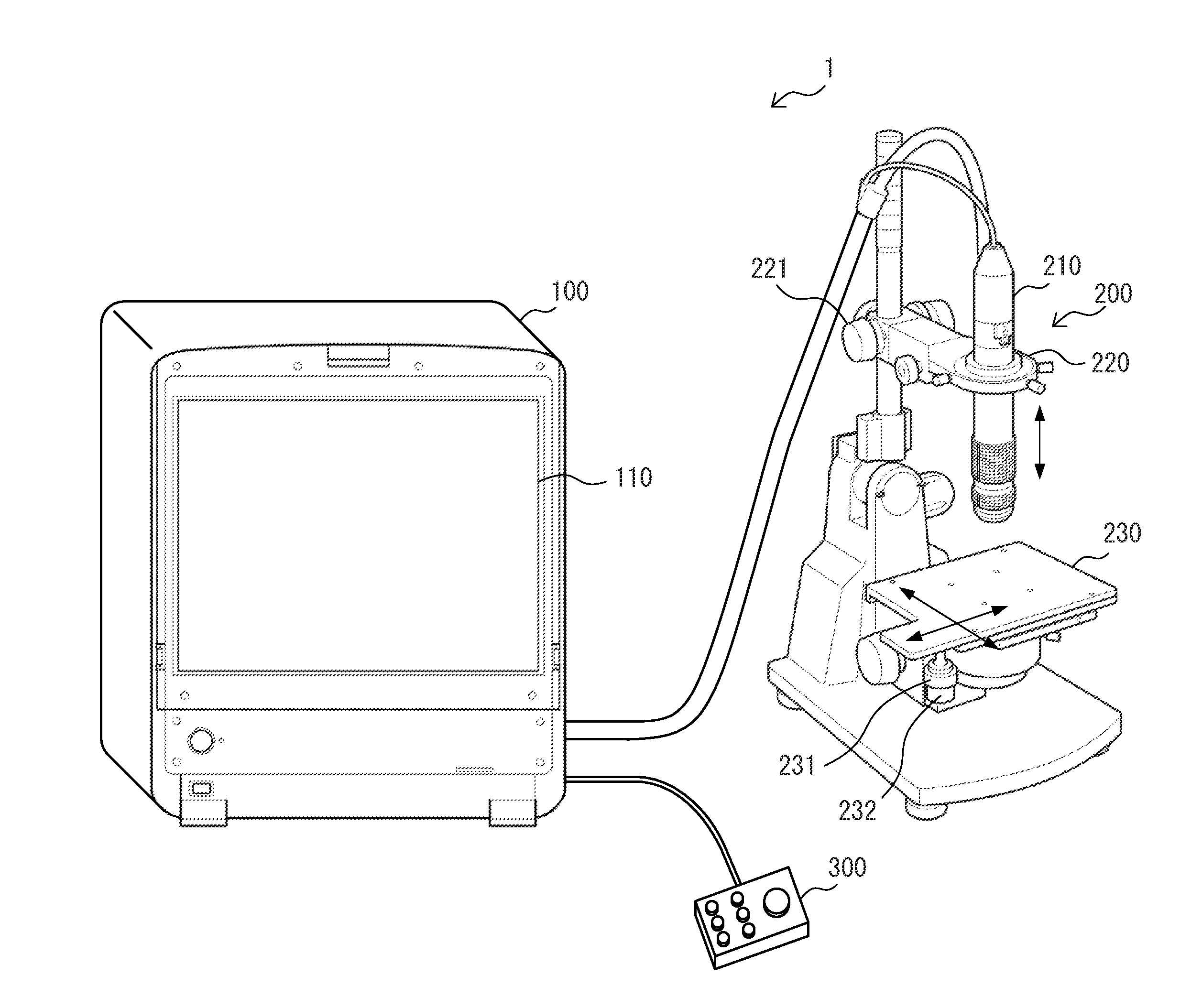
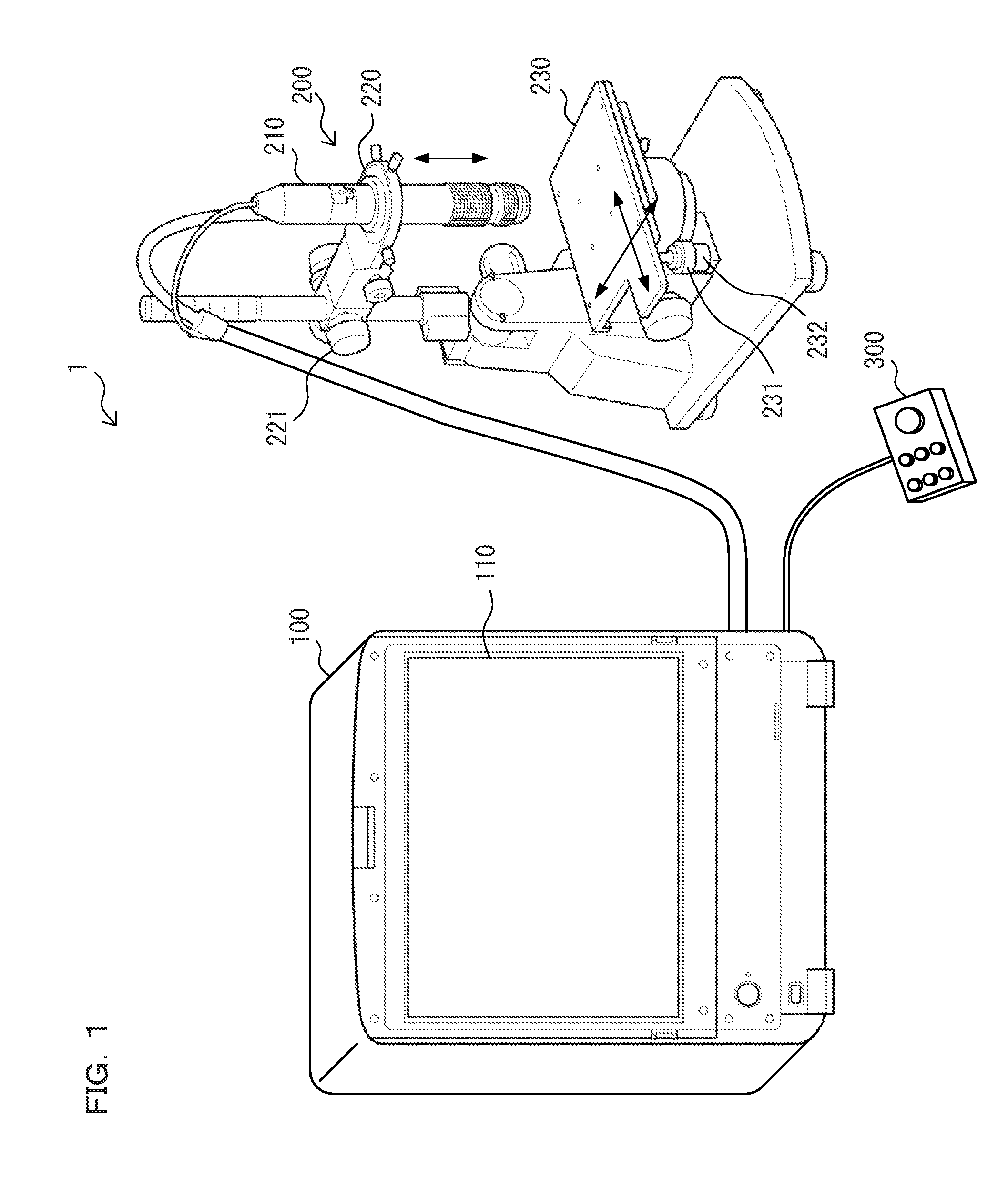
[0031]FIG. 1 is a system view showing an example of a schematic configuration of an imaging device according to a preferred embodiment 1 of the present invention; and as an example of the imaging device, there is shown a magnification observation device 1 which includes a system body 100, a camera unit 200, and a console 300. The magnification observation device 1 is a digital microscope which generates a moving picture image by photographing a photographic subject enlarged by an objective lens and can display the moving picture image on a display unit 110 of the system body 100.

[0032]The camera unit 200 is a photographing unit which is for photographing an object to be inspected while changing a field of view, and includes a camera 210, a movable holder 220, and a movable stage 230. The camera 210 is a read device which photographs the object to be inspected as the photographic subject and generates a moving picture image made o...

embodiment 2

Preferred Embodiment 2

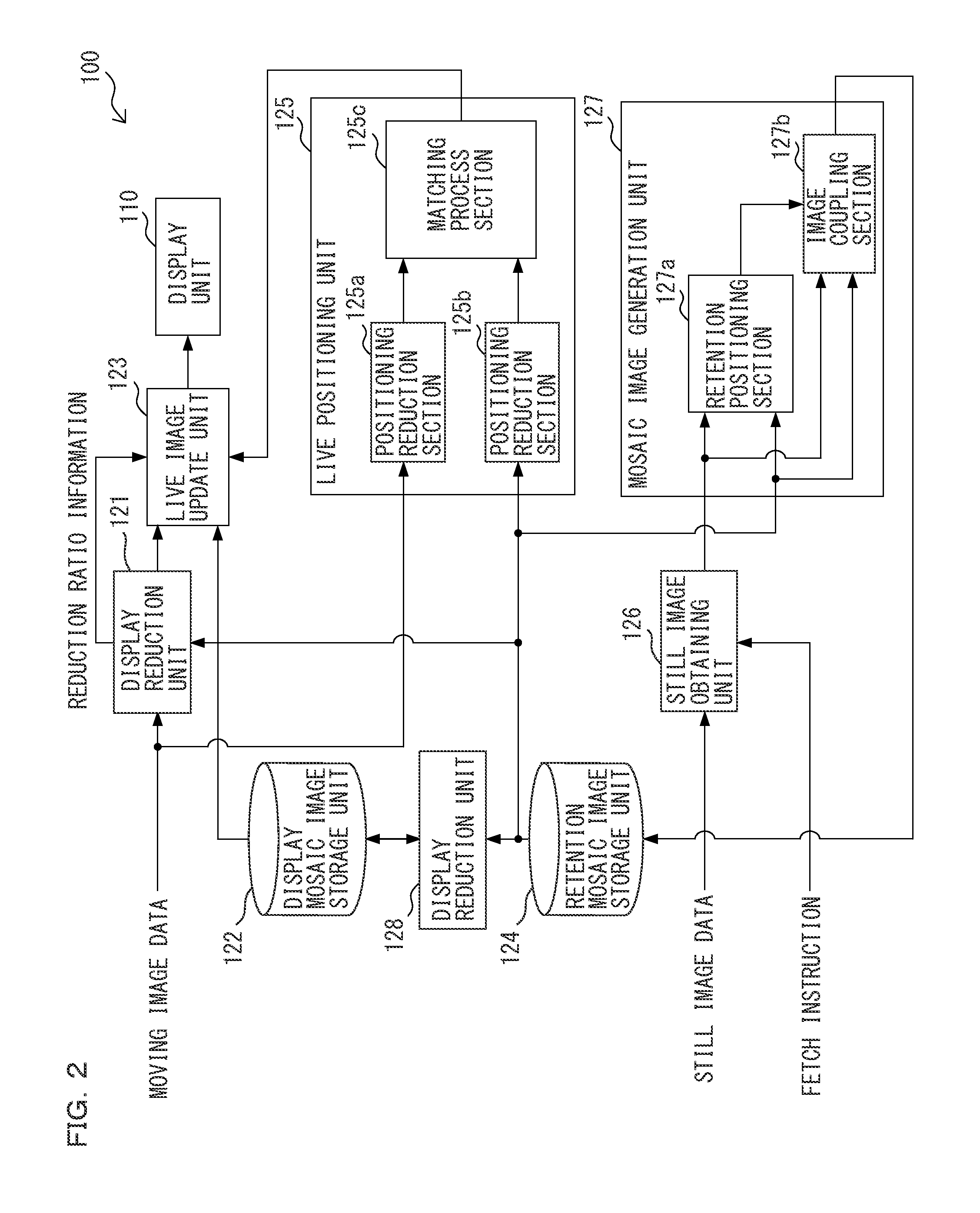
[0099]In the preferred embodiment 1, the description is made about the example where the reduction ratio in the case of reducing the frame image and the retention mosaic image is decided so that the whole of the display mosaic image and the whole of the display frame image are displayed at the same time. On the other hand, in the present preferred embodiment, description will be made on the case where a reduction ratio is fixed when the image size of a mosaic image exceeds a constant size.

[0100]Display reduction units 121 and 128 operate to fix a reduction ratio in the case of reducing a frame image and a retention mosaic image when the image size of a retention mosaic image exceeds a constant size. That is, the reduction ratio is decided so that the whole of the display mosaic image and the whole of the display frame image are displayed in a live screen 111 at the same time and a reduction process is performed until the image size of the retention mosaic image...

embodiment 3

Preferred Embodiment 3

[0105]In the preferred embodiment 1, the description is made about the example where the whole of the display mosaic image and the whole of the display frame image are displayed, the display frame image corresponding to the positioning frame image at any position having the overlap area necessary for determination of the relative position. On the other hand, in the present preferred embodiment, description will be made on the case where a reduction ratio in the case of reducing a frame image and a retention mosaic image is updated each time a display position of a display frame image with respect to a display mosaic image is updated, and the whole of the display mosaic image and the whole of the updated display frame image are displayed.

[0106]Display reduction units 121 and 128 operate to update the reduction ratio in the case of reducing the frame image and the retention mosaic image each time the display position of the display frame image with respect to the...


PUM


Abstract

The present invention provides an imaging device capable of displaying the whole of a display mosaic image in a screen even when the image size of the mosaic image is largely changed, the imaging device including: a mosaic image generation unit which assembles a plurality of still images, and generates the mosaic image; a relative position determination unit which determines a relative position between a frame image and the mosaic image; a display reduction unit which reduces the frame image and the mosaic image respectively based on the image size of the mosaic image, and generates a display frame image and a display mosaic image; and a live image display unit which updates a display position of the frame image with respect to the mosaic image based on a determination result of the relative position.

Description

CROSS REFERENCE TO RELATED APPLICATIONS[0001]The present application claims foreign priority based on Japanese Patent Application No. 2008-317074, filed Dec. 12, 2008, the contents of which is incorporated herein by reference.BACKGROUND OF THE INVENTION[0002]1. Field of the Invention[0003]The present invention relates to imaging devices and, more particularly, relates to an imaging device capable of displaying a moving picture image, which is generated by a camera that photographs an object to be inspected, on a mosaic image that is wider in field of view than an actual field of view of the camera.[0004]2. Description of the Related Art[0005]An image mosaic is known in the related art as a technique which creates a sheet of an image with a wide field of view that is wider in field of view than an actual field of view of a camera by assembling a plurality of still images photographed while changing a field of view. In the case of an imaging device such as a digital microscope which p...

Claims


Application Information

Patent Timeline
IPC IPC(8): H04N5/228
CPCG02B21/365
Inventor KANG, WOOBUM
Owner KEYENCE
Learn More