Hand-held power tool

a power tool and hand-held technology, applied in the direction of luminescence, instruments, light support devices, etc., can solve the problems of workpieces subjected to dirt or debris damage, workpieces are the nose of a tool is more likely to be involved in collisions with other objects, so as to reduce the impact of vibration generated by the tool insert and the overall uniformity of the overall illumination pattern

Active Publication Date: 2010-06-17
ROBERT BOSCH GMBH
View PDF8 Cites 24 Cited by
  • Summary
  • Abstract
  • Description
  • Claims
  • Application Information

AI Technical Summary

Benefits of technology

[0006]A hand-held power is described which may be, for example, a drill / driver or impact driver. The tool is provided with an output shaft rotatable around a tool axis of rotation, a tool housing portion radially disposed relative to the output shaft, an illuminating element for illuminating a work area of the tool, a lens positioned adjacent the illuminating element, and a cover that secures the lens and the illuminating element to the tool housing portion. A portion of the cover is closer to the axis of rotation than the lens is to the axis of rotation. In such a configuration, the cover can actually wrap around the lens so as to better secure the lens and illuminating element to the nose of the tool.
[0007]If at least a portion of tool housing portion is positioned between the output shaft and the lens, the tool housing portion may advantageously protect the illuminating element and lens from the output shaft. Positioning of the tool housing portion in this way provides structural support for the illuminating element and lens while permitting these elements to be moved out radially relative to the axis of rotation in comparison with prior art designs.
[0008]Preferably at least a second illuminating element and at least a second lens are further provided. Multiple illuminating elements have the advantage that shadows created by nearby aspects of the tool nose are cancelled out. That is, one illuminating element might illuminate a portion of the work piece that is lies in a shadow with respect to another illuminating element. Naturally it is preferable if each illuminating element is provided with its own lens element to help guide the light rays and protect the illuminating element.
[0009]If the multiple illuminating elements and multiple lenses are arranged symmetrically about the axis of rotation, the illumination will be more uniformly distributed at the work piece. Because it is impossible to position a light directly along the axis of rotation when using an opaque tool insert, the more illuminating elements that are symmetrically distributed about the axis of rotation, the greater the uniformity of the overall illumination pattern.
[0010]It is preferable to form the cover out of a soft flexible material. This will protect the nose of the tool and any lenses from collisions or contact with foreign objects. Furthermore, since the cover is in contact with the lens and in indirect contact with the illuminating elements and their support member, the cover helps to reduce the impact of vibrations generated by the tool insert while using the tool. When an impact driver or other percussion tool is used, the cover can help to absorb some of the shock generated by engagement of the impact or percussion mechanism.
[0011]If the cover generally surrounds the axial and radial face of the tool housing, then it is not necessary to use additional elements for securing the cover to the housing, since the cover can achieve a snug fit with these elements. This advantage is even better realized if the cover is made of a flexible material.

Problems solved by technology

But this position presents certain design challenges.
If lenses are used, their position close to the work piece subjects them to possible damage from dirt or debris.
In practice, the nose of a tool is more likely to be involved in collisions with other objects such as the work piece itself.
During use, vibrations are generated by the action of the tool insert.
In the case of an impact driver, the impact mechanism is nearby, creating shocks in the tool nose.
Such vibrations and shocks may compromise the stability and durability of the illumination assembly.

Method used


Image

  • Hand-held power tool
  • Hand-held power tool
  • Hand-held power tool

Examples


Embodiment Construction

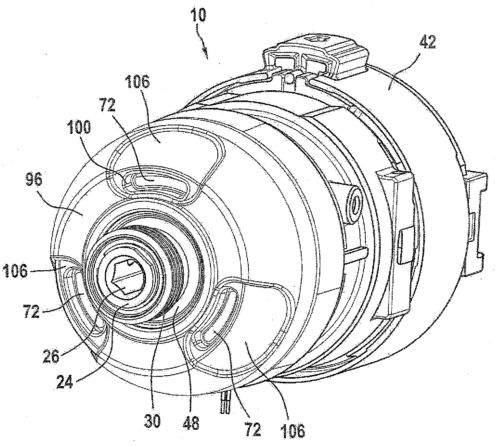
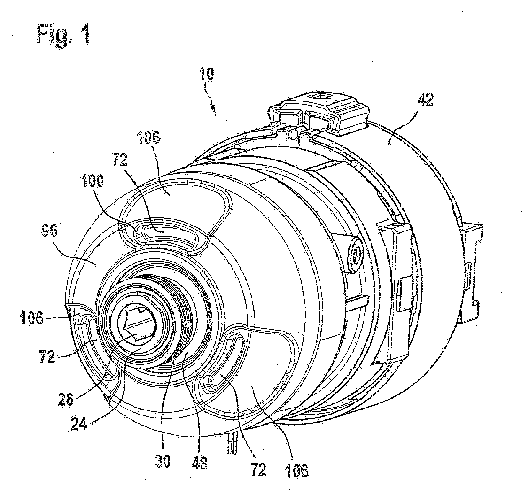
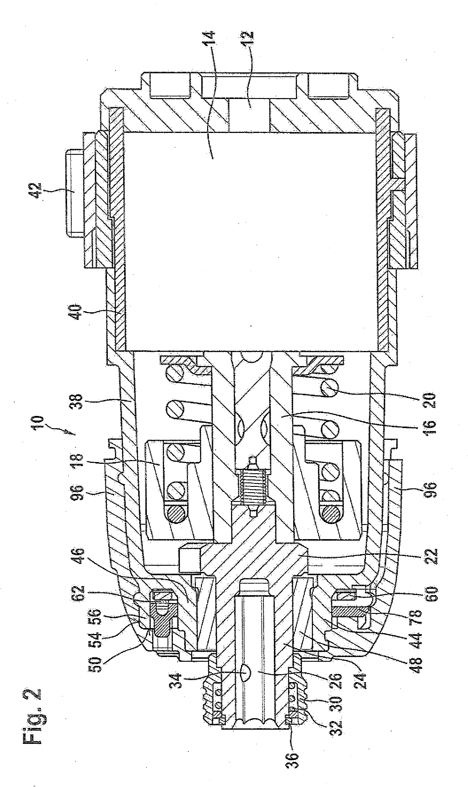
[0028]Just the nose portion 10 of a hand-held power tool of the sort used for drilling and / or driving is shown in FIGS. 1 and 2. Since these tools are commonplace, aspects of these tools not relevant to the invention, such as a handle, motor and motor housing are not illustrated. The tool may be provided either with a power cord for drawing AC power or may incorporate an intrinsic or removable rechargeable DC battery.

[0029]Torque from the motor is transmitted via a pinion gear 12 through a gear transmission 14 to rotate an intermediate shaft 16. Since the illustrated tool is an impact driver, it is provided with a conventional impact mechanism assembly comprising among other things a striker 18, a spring 20 and an anvil 22 for providing high torque impacts. Anvil 22 is integral with an output shaft 24 which is provided with a cavity 26 for receiving a tool insert. Output shaft 24 rotates around a tool axis of rotation 28 (FIG. 4) and is provided with a sleeve 30, a spring 32, a lock...


PUM


Abstract

A hand-held power tool comprising an output shaft rotatable around a tool axis of rotation, a tool housing portion radially disposed relative to the output shaft, an illuminating element for illuminating a work area of the tool, a lens positioned adjacent the illuminating element, and a cover that secures the lens and the illuminating element to the tool housing portion. At least a portion of the cover is closer to the axis of rotation than the lens is to the axis of rotation.

Description

CROSS-REFERENCE TO RELATED APPLICATION[0001]This application is based on EP Application 08105996.6 filed on Dec. 16, 2008.BACKGROUND OF THE INVENTION[0002]1. Field of the Invention[0003]The present invention relates to means for illuminating the work area of a hand-held power tool. It has become common for hand-held power tools to include integrated illumination means to permit use even under poor lighting conditions. However it is has been challenging from a design standpoint to simultaneously achieve effective illumination of the work area alongside other design goals, since these hand-held tools should also be compact, light, and especially in the case of cordless tools, energy efficient.[0004]2. Description of the Prior Art[0005]One solution directed towards drilling / driving tools involves positioning small and lightweight LED's as near as possible to the tool insert for illuminating the immediately adjacent work area. For example, US 2008 / 0074865 A1 describes incorporating a PC...

Claims


Application Information

Patent Timeline
Patent Type & Authority Applications(United States)
IPC IPC(8): B25B23/18
CPCB25F5/021B25B23/18B25B21/02
Inventor LEONG, CHI HOE
Owner ROBERT BOSCH GMBH
Why Eureka
Try Eureka