Double-sided indexable face milling insert

a technology of indexable face and insert, which is applied in the direction of turning machine accessories, shaping cutters, manufacturing tools, etc., can solve the problems of secondary edge surfaces, pronounced chip formation and chip evacuation, and particularly blunt cutting

Active Publication Date: 2010-06-17
SANDVIK INTELLECTUAL PROPERTY AB
View PDF29 Cites 43 Cited by
  • Summary
  • Abstract
  • Description
  • Claims
  • Application Information

AI Technical Summary

Benefits of technology

[0011]Another object of the invention is to provide a face milling insert, in which the desired, cutting-technical improvements can...

Problems solved by technology

The negative axial tipping in of the milling insert gives rise to, on one hand, greater axial cutting forces than those cutting forces that arise when the milling inserts are positively tipped in, and, on the other hand, difficult-to-master problems with the chip formation as well as the chip evacuation, among other things so far that the chips tend to be directed obliquely downward toward the generated plane surface rather than escaping therefrom.
The problems caused by the negative axial and radial tipping-in, respectively, are particularly accentuated in milling cutters having older type milling inserts, which have a prismatic basic shape and include cutting edges, the main edges of which are straight and pair-wise parallel along their common clearance surfaces, as are also the secondary edges straight and pair-wise parallel along the common clearance surfaces thereof In this case, the main edges become particularly blunt-cutting and give rise to pronounced chip formation and chip evacuation problems, because they have to be tipped in at a great negative axial angle to give the desired, efficient cl...

Method used


Image

  • Double-sided indexable face milling insert
  • Double-sided indexable face milling insert
  • Double-sided indexable face milling insert

Examples


Embodiment Construction

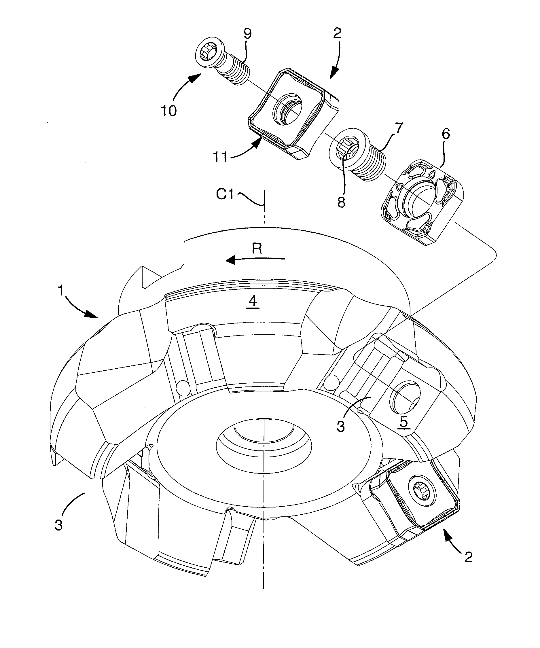
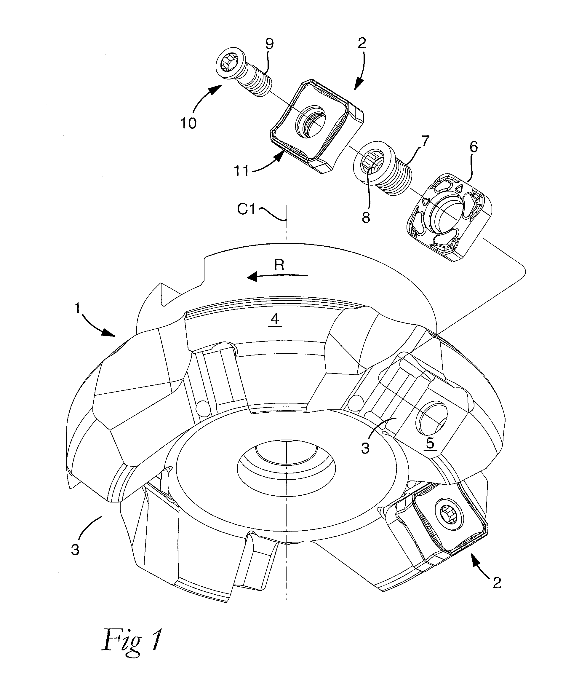
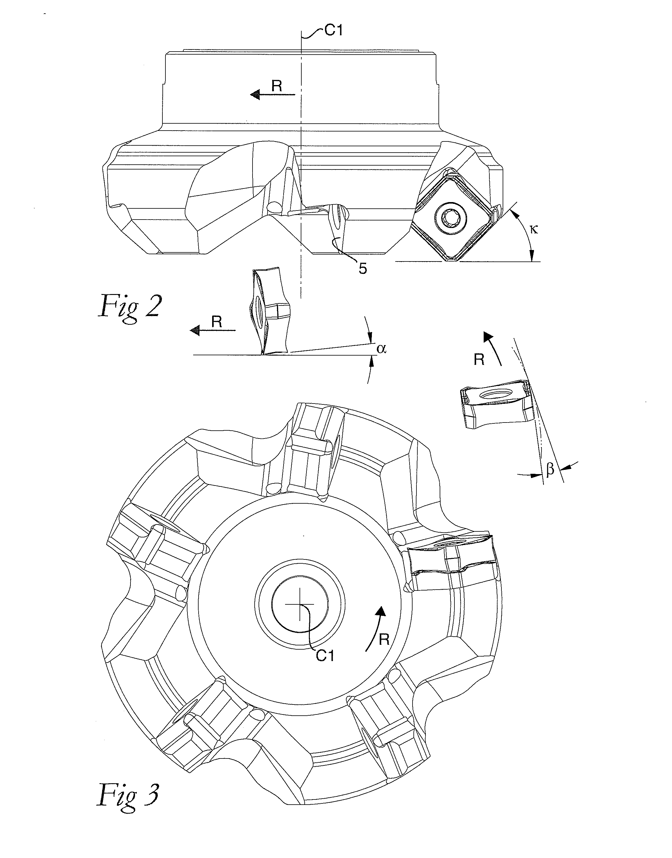
[0033]In FIGS. 1-3, a milling tool is exemplified in the form of a face mill, which is composed of a basic body or milling cutter body 1 and a number of replaceable milling inserts 2. The milling cutter body 1 is rotatable in the direction of rotation R around a center axis designated C1, and includes, in a front or lower end, a number of chip pockets 3 for each one of the milling inserts 2. In the example, the number of chip pockets amounts to five. The chip pockets 3 are recessed in a rotationally symmetrical envelope surface 4 and include a seating or insert seat, which is represented by a plane bottom surface 5. Although it is fully possible to apply the individual milling insert directly against the bottom surface 5, in this case a shim plate 6 is arranged between the bottom surface 5 and the milling insert 2. This shim plate is kept semi-permanently fixed against the bottom surface 5 by a tube screw 7, in the female thread 8 of which a male thread 9 of a screw 10 can be tighte...


PUM

PropertyMeasurementUnit
Angleaaaaaaaaaa
Angleaaaaaaaaaa
Angleaaaaaaaaaa

Abstract

A double-sided, indexable face milling insert, including an upperside, an underside, and a neutral plane (NP) parallel to the upperside and the underside, the neutral plane forming a right angle with a geometrical center axis (C2). A plurality of indexable cutting edges are formed along circumferential borderlines in transitions between a number of clearance surfaces and the upperside as well as the underside. Each cutting edge includes a chip-removing main edge and a surface-wiping secondary edge, the secondary edge forming an obtuse angle with the main edge in plane view. A corner clearance surface extends between and connects each pair of upper and lower secondary edges, the corner clearance surface including first and second part surfaces which each form an acute angle (η) in side elevation view with respective reference planes (RP) parallel to the neutral plane.

Description

[0001]This application claims priority under 35 U.S.C. §119 to Swedish Patent Application No. 0850145-4, filed on Dec. 17, 2008, which is incorporated by reference herein in its entirety.FIELD OF THE INVENTION[0002]The present invention relates generally to a double-sided and indexable face milling insert of the type that includes an upperside and an underside, a neutral plane parallel to the same, as well as a plurality of alternately applicable cutting edges, which are formed along circumferential borderlines in transitions between a number of clearance surfaces and the upperside as well as the underside, and which individually include a chip-removing main edge and a surface-wiping secondary edge, which—as viewed in planar view—forms an obtuse angle with the main edge.BACKGROUND OF THE INVENTION[0003]Milling tools for chip removing machining of, above all, workpieces of metal (steel, aluminium, titanium, etc.) are generally composed of a rotatable basic body or milling cutter body...

Claims


Application Information

Patent Timeline
IPC IPC(8): B23C5/20B23B27/22
CPCB23C5/207B23C5/2208B23C2200/083B23C2200/125B23C2200/162Y10T407/1962B23C2210/166B23C2210/168Y10T407/1924Y10T407/235Y10T407/23B23C2200/208B23C5/202B23C5/06B23B27/16B23C5/20
Inventor OPRASIC, AMILWIHLBORG, LENNARTWIDIN, LEIFROMAN, STEFAN
Owner SANDVIK INTELLECTUAL PROPERTY AB
Why Eureka
Try Eureka