Eureka AIR delivers breakthrough ideas for toughest innovation challenges, trusted by R&D personnel around the world.

Rechargeable battery

Inactive Publication Date: 2010-06-17
SAMSUNG SDI CO LTD
View PDF1 Cites 13 Cited by
  • Summary
  • Abstract
  • Description
  • Claims
  • Application Information

AI Technical Summary

Benefits of technology

[0011]The present teachings provide a rechargeable battery that has improved resistance to vibration and shock.
[0018]As described above, according to various embodiments of the present teachings, a rib is formed on an insulating member, to thereby stably support a current collecting plate and a electrode assembly. As a result, an electrical contact between the current collecting plate and the electrode assembly, or an electrical contact between the current collecting plate and the cap assembly, are prevented from being damaged by external forces, to thereby improve the stability of a rechargeable battery.
[0019]According to aspects of the present teachings, the contact resistance between the current collecting plate and the electrode assembly, or between the current collecting plate and the cap assembly, is prevented from being increased, to thereby improve output.

Problems solved by technology

When external forces, such as shocks or vibrations, are transmitted to a rechargeable battery, the electrical contacts of the current collecting plates may be damaged.
When an electrical contact in a welded part is damaged, resistance increases, such that the output of the rechargeable battery may decrease, and when the welded part is disconnected, the current cannot be transmitted to the outside.

Method used


Image

  • Rechargeable battery
  • Rechargeable battery
  • Rechargeable battery

Examples


Embodiment Construction

[0029]Reference will now be made in detail to the exemplary embodiments of the present teachings, examples of which are illustrated in the accompanying drawings, wherein like reference numerals refer to the like elements throughout. The exemplary embodiments are described below, in order to explain the aspects of the present teachings, by referring to the figures.

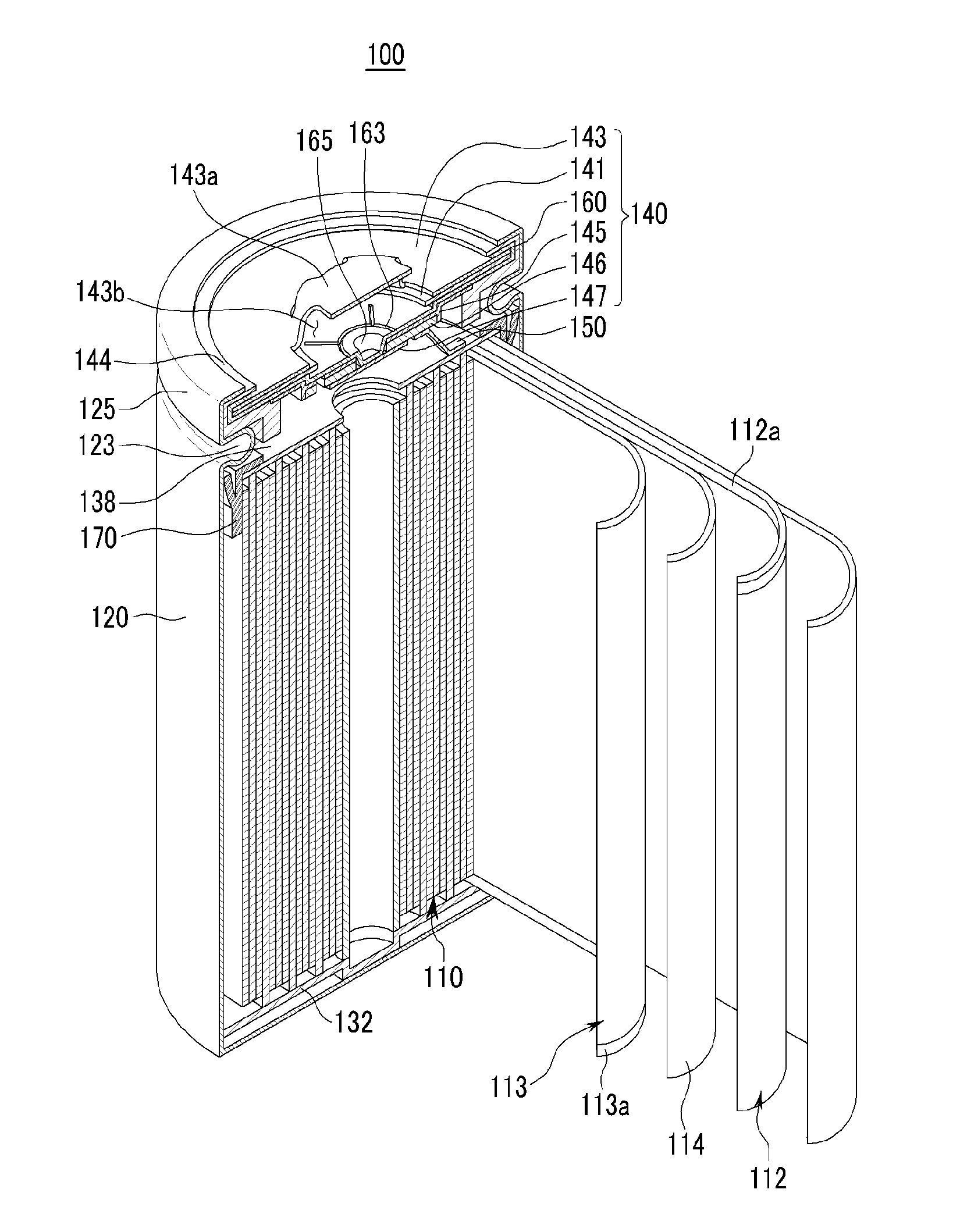
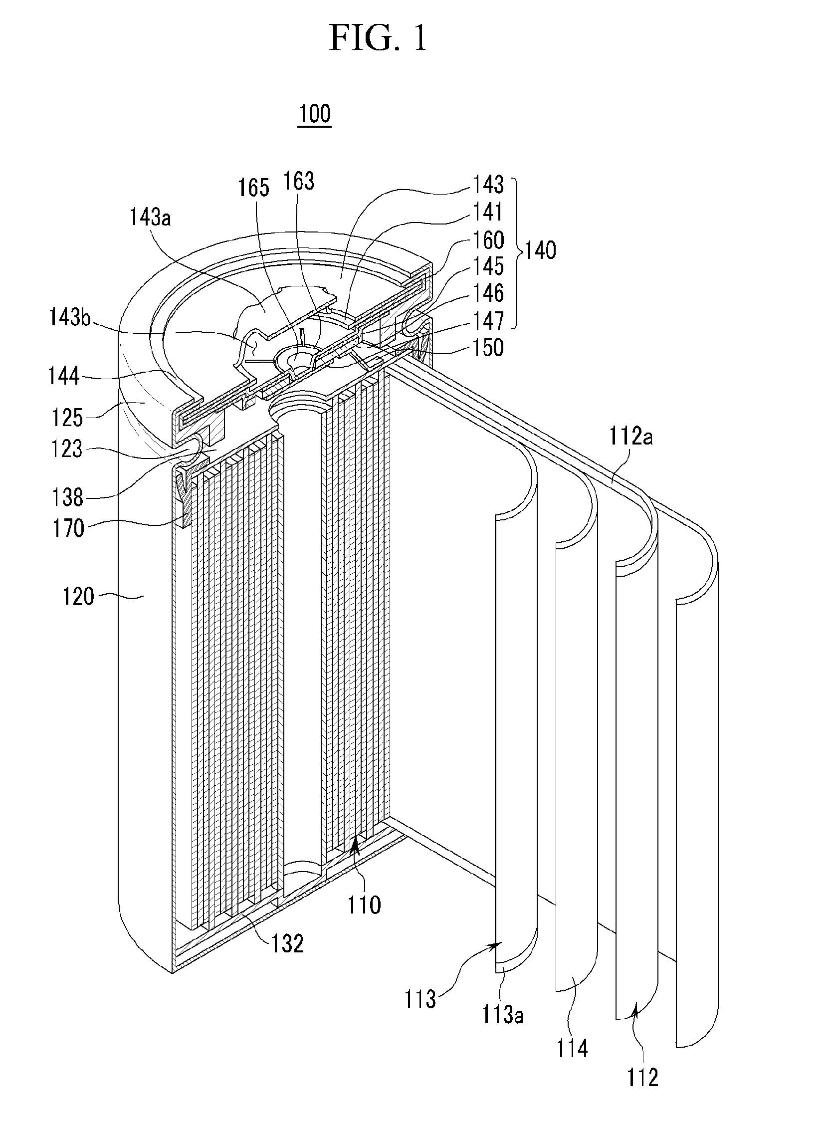
[0030]FIG. 1 is a cross-sectional perspective view of a rechargeable battery 100, according to a first exemplary embodiment of the present teachings. Referring to FIG. 1, the rechargeable battery 100 includes: an electrode assembly 110; a case 120 to house the electrode assembly 110 and an electrolytic solution; and a cap assembly 140 to seal an opening of the case 120, via a gasket 144. The electrode assembly 110 includes a positive electrode 112, a negative electrode 113, and a separator 114 interposed therebetween.

[0031]Herein, an upper end of the rechargeable battery 100 refers to the end where the cap assembly 140 is d...


PUM


Abstract

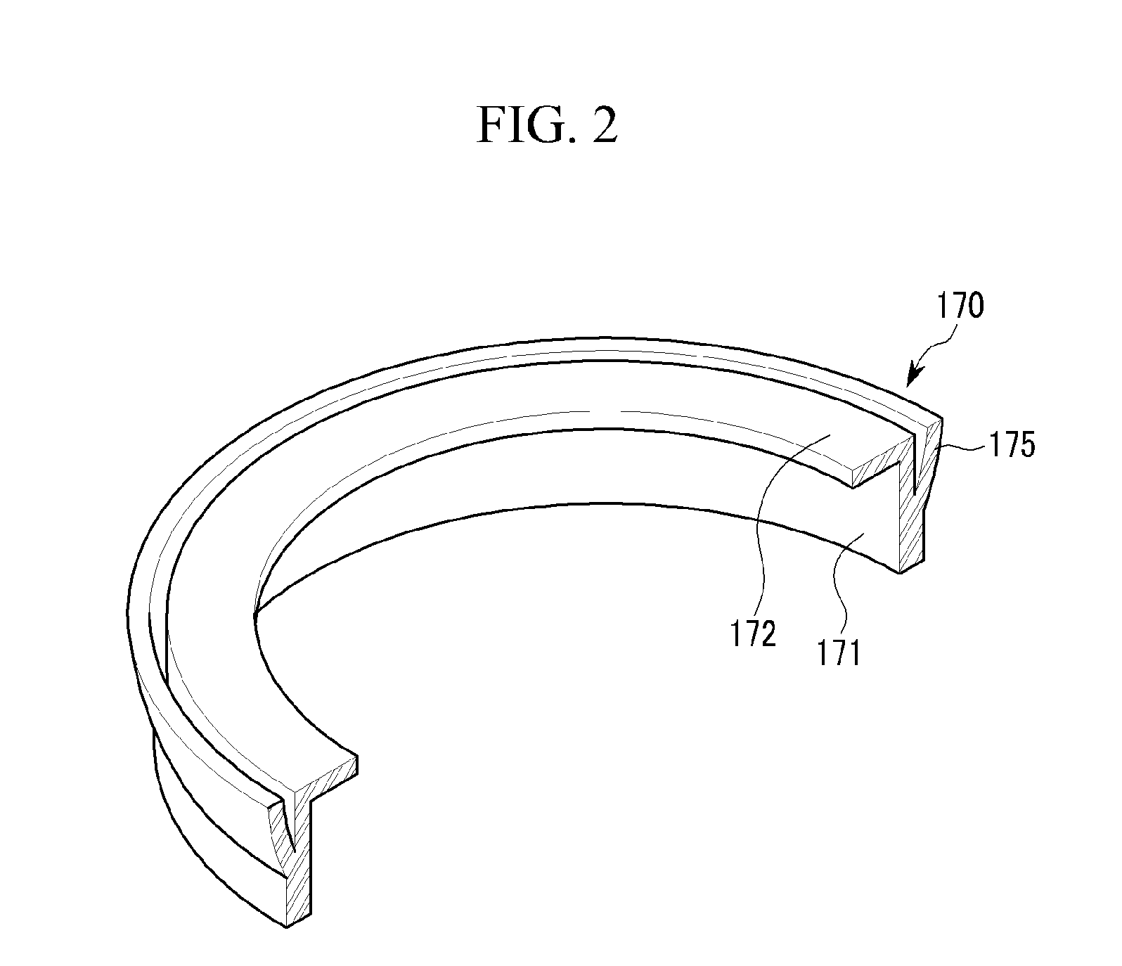
A rechargeable battery including: an electrode assembly that includes a positive electrode, a negative electrode, and a separator interposed therebetween; a case to house the electrode assembly; a cap assembly that is coupled to an opening of the case and electrically connected with the electrode assembly; and an insulating member that is installed between the case and the electrode assembly. The insulating member includes a body disposed on the electrode assembly and a rib that extends from the body and contacts the case.

Description

CROSS-REFERENCE TO RELATED APPLICATION[0001]This application claims the benefit of Korean Patent Application No. 10-2008-0126775 filed on Dec. 12, 2008, in the Korean Intellectual Property Office, the disclosure of which is incorporated herein by reference.BACKGROUND[0002]1. Field[0003]The present teachings relate to a rechargeable battery.[0004]2. Description of the Related Art[0005]Rechargeable batteries can be repeatedly charged and discharged, unlike primary batteries. A low-capacity rechargeable battery constituted by one cell is used for a small portable electronic device, i.e., a mobile phone, a laptop computer, or a camcorder. A large-capacity rechargeable battery, constituted by a plurality of cells connected to each other in a pack, is widely used for a power supply of a hybrid electric vehicle.[0006]Rechargeable batteries are manufactured in various shapes. Exemplary shapes may include a cylindrical shape, a prismatic shape, etc. For high power applications, rechargeable ...

Claims


Application Information

Patent Timeline
IPC IPC(8): H01M2/02H01M50/107H01M50/159H01M50/167
CPCH01M2/0413H01M2/0482Y02T10/7011H01M10/052H01M10/0587H01M10/0431Y02E60/10H01M50/171Y02P70/50H01M50/159H01M50/167H01M50/107H01M50/593H01M50/586H01M50/538Y02T10/70
Inventor KIM, YONG-SAMHAN, DAE-WON
Owner SAMSUNG SDI CO LTD
Why Eureka
Eureka Blog
Learn More