A transmission mechanism for a microwave switch

A microwave switch and transmission mechanism technology, applied to waveguide devices, electrical components, circuits, etc., can solve the problems of difficulty in meeting the transmission requirements of high-power microwave switches and limited reed stroke amplification, and achieve small space occupation and effective improvement. load, and the effect of improving the vibration and shock resistance performance

Active Publication Date: 2018-07-24
CHINA AEROSPACE TIMES ELECTRONICS CORP
View PDF3 Cites 0 Cited by
  • Summary
  • Abstract
  • Description
  • Claims
  • Application Information

AI Technical Summary

Problems solved by technology

[0003] The driving piece used in the existing mechanical coaxial microwave switch is a planar driving piece. This type of driving piece is fixed on the armature group. The driving piece drives the driving rod and the reed to move downward with the rotation of the armature. The structure of the driving piece The limitation of the reed stroke is limited, and it is difficult to meet the transmission requirements of the large stroke of the high-power microwave switch.

Method used


Image

  • A transmission mechanism for a microwave switch
  • A transmission mechanism for a microwave switch
  • A transmission mechanism for a microwave switch

Examples


Embodiment Construction

[0028] The present invention will be described in detail below in conjunction with the accompanying drawings.

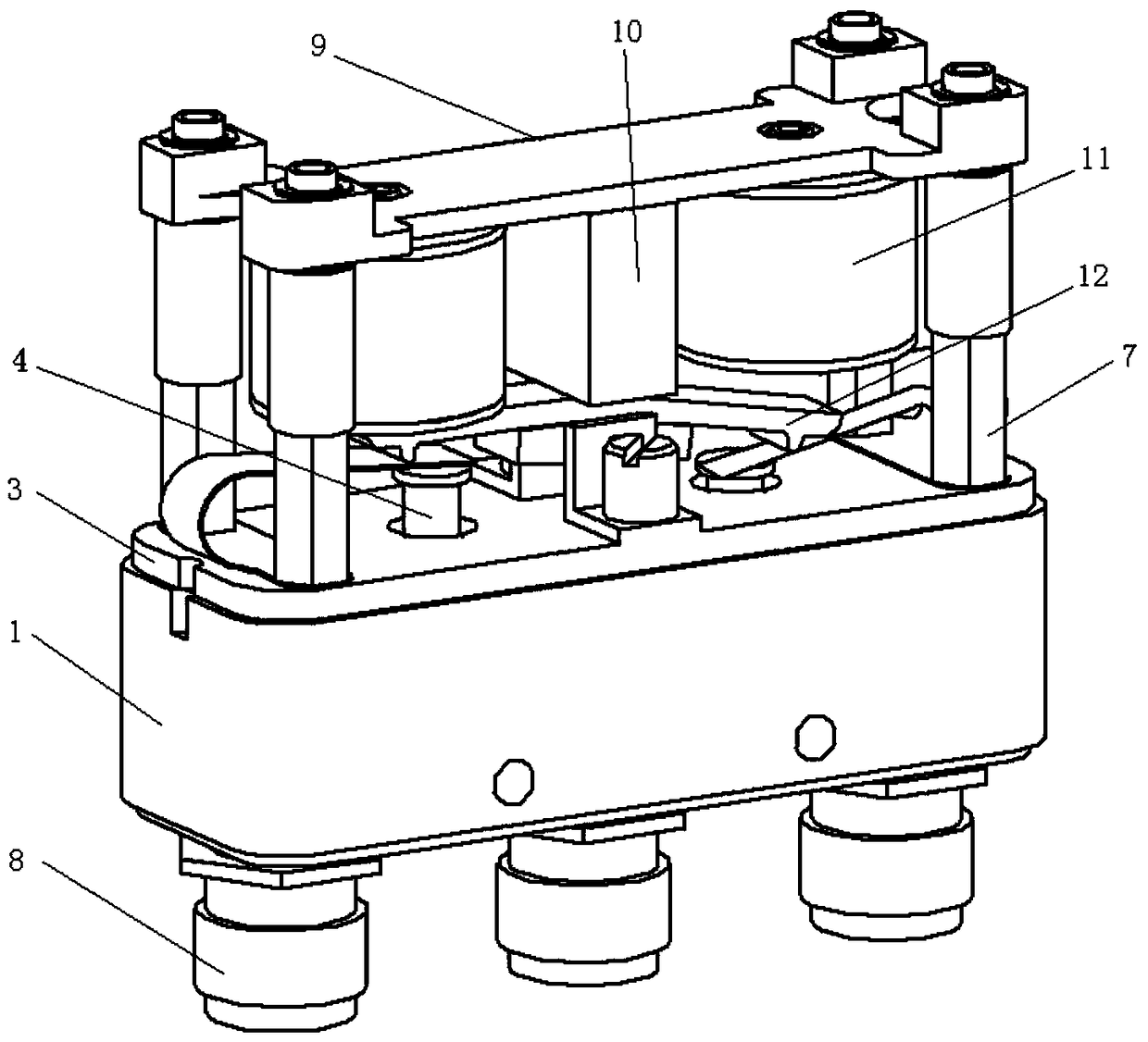
[0029] A transmission mechanism for a microwave switch, such as figure 1 As shown, including electromagnetic group, armature group and guide system,

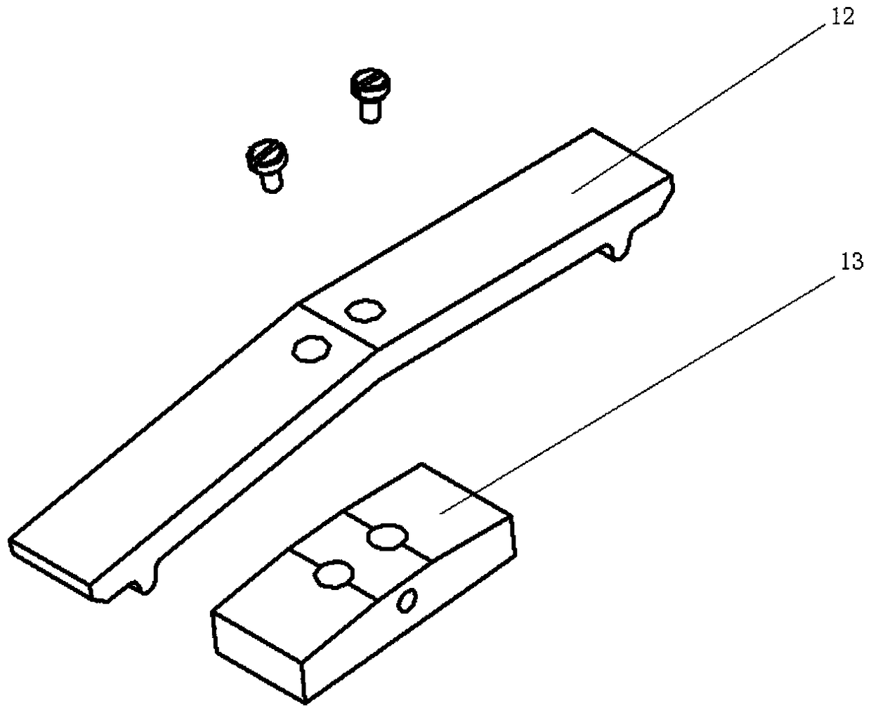
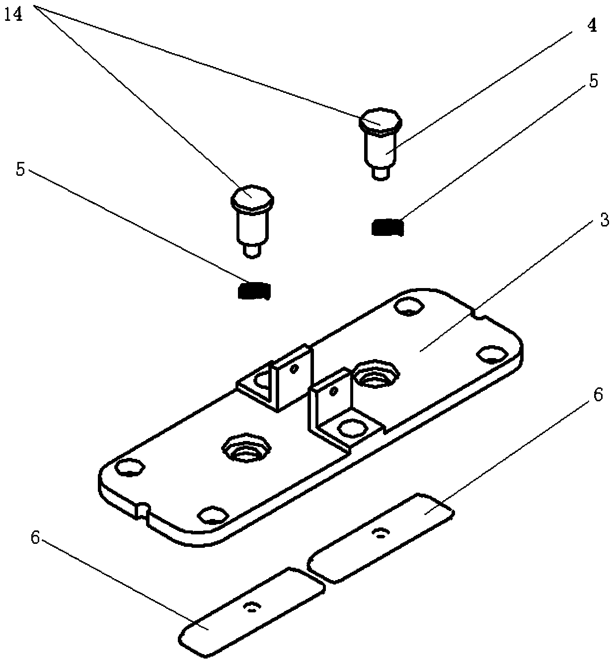
[0030] The guide system includes a base 1, two J-shaped driving pieces 2, a cover plate 3, two driving rods 4, two compression springs 5, two reeds 6, four supporting studs 7 and three joints 8, Such as Figure 3-5 As shown, the base 1 is a hollow cavity, and its bottom surface is provided with a through hole connected with the joint 8. One end of the joint 8 is placed in the cavity of the base 1, and the other end is placed outside the base 1. The cover plate 3 on the top of the base 1 has a through hole, and one end of the drive rod 4 is provided with a limit plate 14, and the clip spring 5 is set on the drive rod 4 and is limited by the limit plate 14 and the cover plate 3. Each drive rod 4 One end is put on the ...


PUM


Abstract

The invention discloses a transmission mechanism for a microwave switch. Driving plates are J type spring plates and include long sides and short sides; the long sides and the short sides are connected based on arc structures; lug plates with through holes are arranged on the short sides and the short sides are connected to a cover plate by support bolts; and the long sides are arranged between an armature group and driving rods. A permanent magnet, a magnetic conductive plate, and iron cores of a left coil group and a right coil group form an enclosed magnetic circuit for generate magnetic forces; and the generated magnetic forces are applied to the armature group. An armature has a V-shaped structure; the armature and a carrying and touch body are fixedly connected; protruding lugs in contact with the driving plates are arranged at the lower sides of the two ends of the armature, so that the strokes of the driving rod can be enlarged. According to the invention, the strokes of the driving rods can be effectively enlarged; and on the premise that the effective stroke is realized, the appearance dimension of the product and the product complexity are reduced.

Description

technical field [0001] The invention relates to a transmission mechanism, in particular to a transmission mechanism for a microwave switch, which belongs to the field of mechanical design. Background technique [0002] The main function of the mechanical microwave switch for aerospace is to realize the transmission and switching of the microwave signal path of the satellite system. It is a device that uses vacuum isolation and switches microwave signals through mechanical actions. It is an important part of the microwave communication system and an important, necessary and irreplaceable key component of the microwave link in the entire microwave system. Its main function is to select microwave signal routing and improve the flexibility of system function combination; second is to build a microwave transmission loop to back up microwave equipment and stand-alone devices with high failure rates to improve the reliability of the entire system. [0003] The driving piece used i...

Claims


Application Information

Patent Timeline
Patent Type & Authority Patents(China)
IPC IPC(8): H01P1/11
CPCH01P1/11
Inventor 田亚伟苌群峰张楚贤王文涛姜东明禹继芳
Owner CHINA AEROSPACE TIMES ELECTRONICS CORP
Why Eureka
Try Eureka