
Method for Determining the Speed of an Aircraft

a technology for aircraft and speed, applied in the direction of vehicle position/course/altitude control, process and machine control, instruments, etc., can solve the problem of not meeting time constraints

Active Publication Date: 2010-06-17
THALES SA
View PDF19 Cites 17 Cited by
  • Summary
  • Abstract
  • Description
  • Claims
  • Application Information

AI Technical Summary

Problems solved by technology

One of the drawbacks of such a system arises when a time constraint cannot be complied with.

Method used


Image

  • Method for Determining the Speed of an Aircraft
  • Method for Determining the Speed of an Aircraft
  • Method for Determining the Speed of an Aircraft

Examples


Embodiment Construction

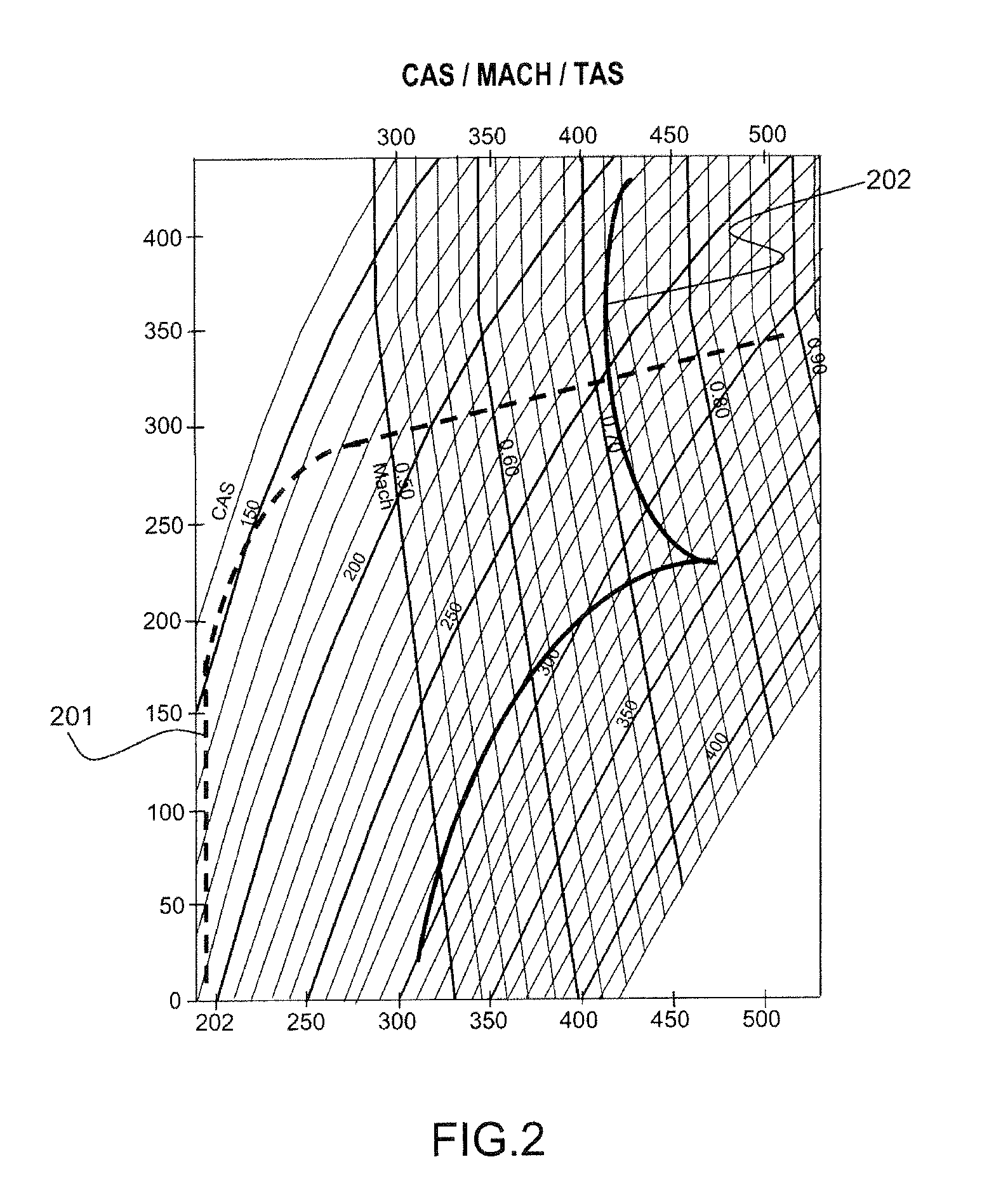
[0044]The abscissa axis represents true air speeds (or TAS for True AirSpeed). The ordinate axis represents altitudes in feet (or ft).

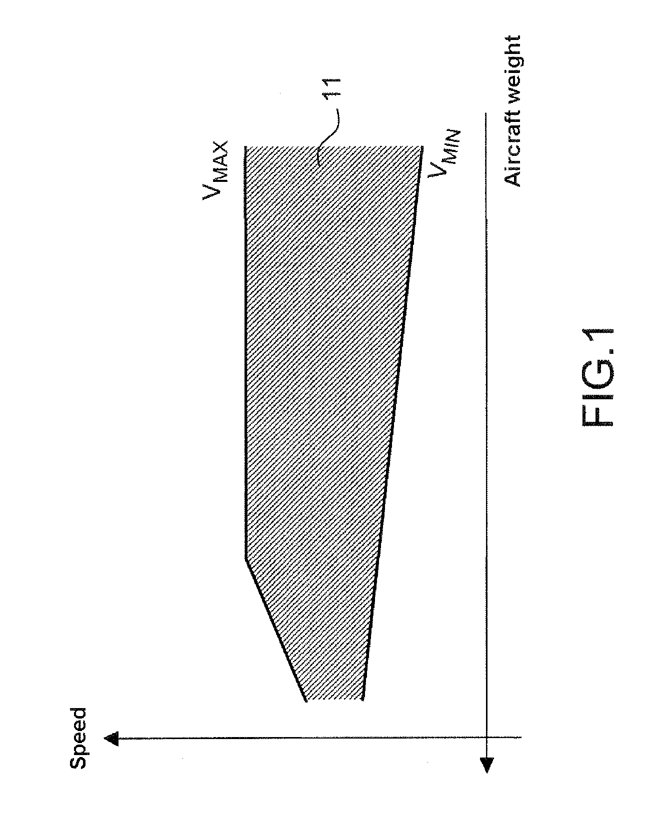
[0045]The curves of minimum air speed Vmin 301 and maximum air speed Vmax 302 of the figure correspond to a case of initial weight GW0 and take account of the lightening of the aircraft weight (this is why for example the CAS parts are not ISO CAS).

[0046]The CAS and MACH setpoints, calculated with the schemes according to the known art, are limited by the envelope. Each of these limits by the envelope is calculated for a single point of the envelope. In the example, the CAS setpoint is limited by the envelope at its value at 22 000 ft to 320 knots (or kts). There exists a first margin 305 between a curve with constant CAS 304 passing through the limit point 303 and the maximum speed Vmax curve 302. This margin 305 is situated at the altitudes below the altitude of limitation by the envelope of 22 000 ft. The first margin 305 represents ranges of speed...


PUM


Abstract

The invention relates to a method for determining the speed of an aircraft that is subject to a time constraint. The invention consists no longer in calculating a single CAS / MACH pair during climb / descent but in adapting the speed in a continuous manner to the bounds of curves of minimum Vmin and maximum Vmax speed defining a flight envelope of the aircraft. The calculation of these speeds is carried out on the basis of constant maximum and minimum speed setpoints and of a coefficient taking into account a deviation to the time constraint.

Description

PRIORITY CLAIM[0001]This application claims priority to French Patent Application Number 08 06232, entitled Method for Determining the Speed of an Aircraft, filed on Nov. 7, 2008.TECHNICAL FIELD[0002]The invention relates to the determination of the speed of an aircraft that is subject to a time constraint.BACKGROUND OF THE INVENTION[0003]For a few years, thoughts have turned to the increase in traffic and the ensuing loading of air traffic controllers. In order to guarantee the safety and also the economic viability of air transport, it is envisaged, notably in the approach phase, that a time constraint be imposed on a particular waypoint: runway threshold, Initial Approach Fix (IAF), or rallying point for final approach, termed the ATC Merge Point.[0004]This allows the air traffic control to guarantee a smoothed flow in the approach, and to manage a stable number of aeroplanes corresponding to the capabilities of the ground facilities and to the limit loading of an air traffic con...

Claims


Application Information

Patent Timeline
IPC IPC(8): G05D1/00G06F17/00
CPCG08G5/0043G05D1/0202
Inventor COULMEAU, FRANCOISGUTIERREZ-CASTANEDA, MANUELSIMI, NICOLASBLANCHON, XAVIER
Owner THALES SA
Learn More