
Machine gun accessory mount

a technology for accessories and machine guns, applied in the field of combat weapons, can solve the problems of obscuring the view of the field of fire of the gunner by a whiteout effect, and achieve the effect of reliably mounting a variety of target sightings and illuminating accessories

Active Publication Date: 2010-06-24
SUREFIRE LLC
View PDF22 Cites 65 Cited by
  • Summary
  • Abstract
  • Description
  • Claims
  • Application Information

AI Technical Summary

Benefits of technology

[0009]In accordance with the present disclosure, universal, light weight, yet robust heavy machine gun accessory mounts are provided that are capable of withstanding harsh environmental conditions and the shock and vibr

Problems solved by technology

While these previous gun accessory mounts address some of the above accessory-to-gun integration issues to some extent, they are not without certain drawbacks when applied to heavy machine guns such as the M2HB, including that some cannot be used with guns having ballistic shields, some have clamping lugs that do not accommodate the various gun shroud hole patterns found in different models of heavy machine guns without some modification of the shroud and / or the lugs, some cannot be used with guns that incorporate a quick change barrel (QCB), and some locate a spotlight accessory at a position relative to the barrel of the gun such that extensive firing of the gun can result in the gunner's view of the field of fire being obscured by a “whiteout” effect.

Method used


Image

  • Machine gun accessory mount
  • Machine gun accessory mount
  • Machine gun accessory mount

Examples


Embodiment Construction

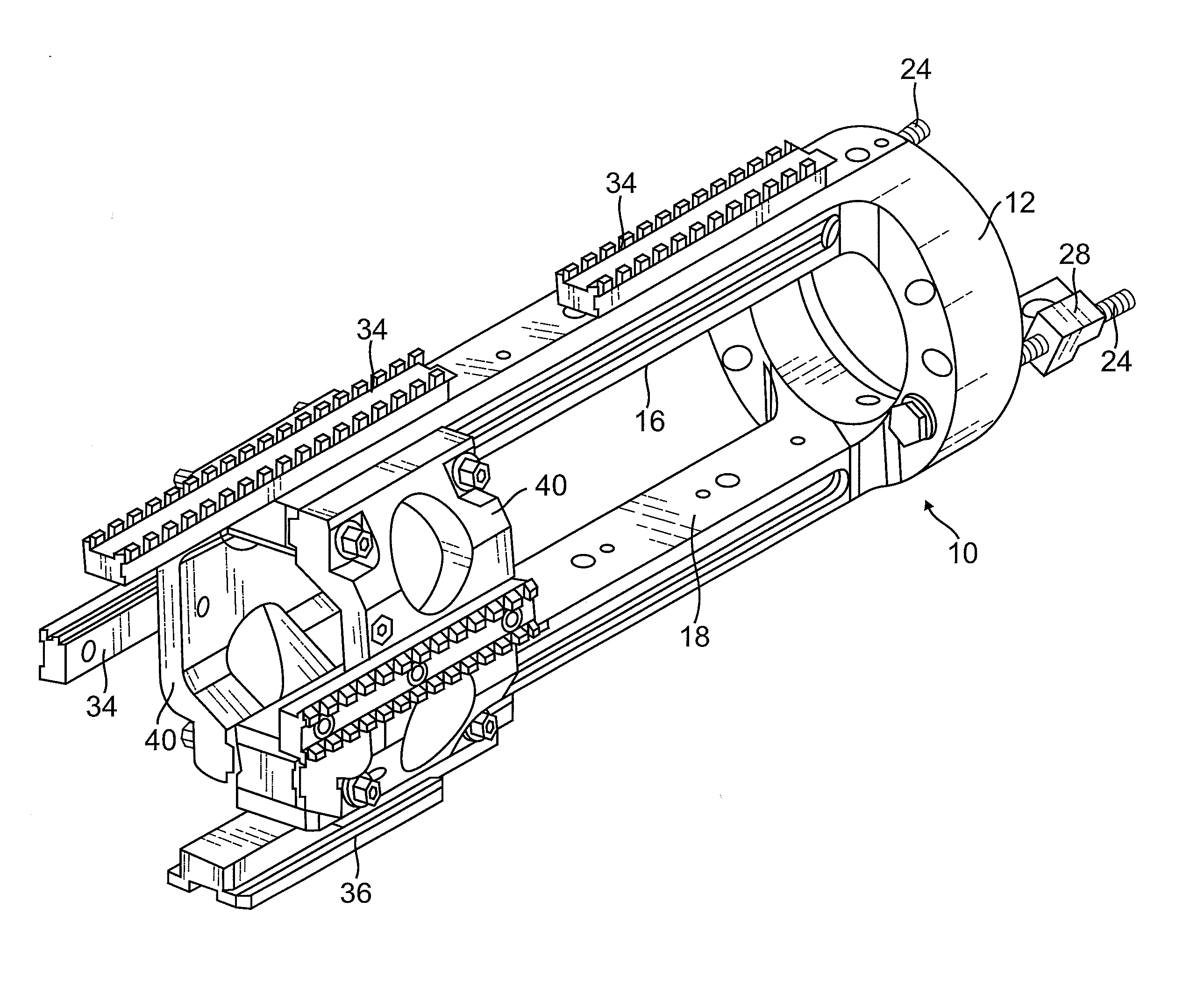
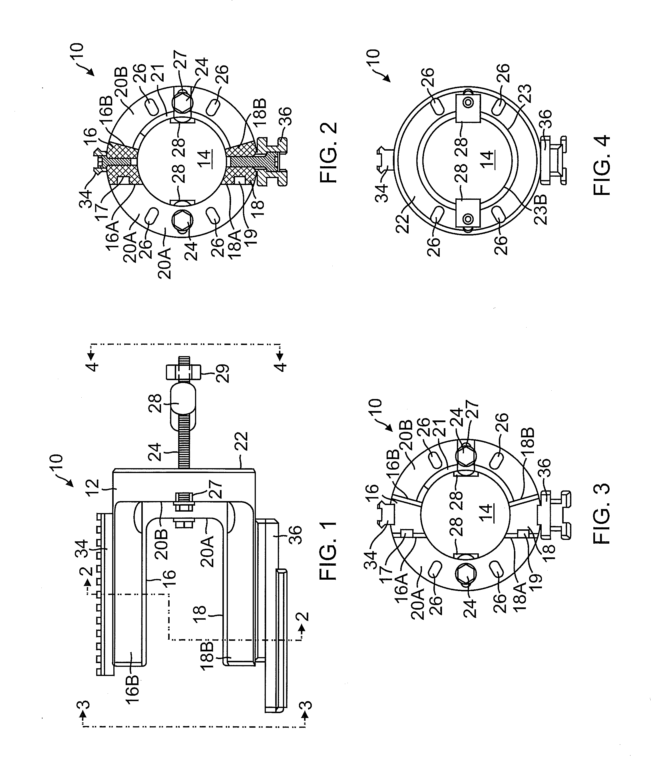
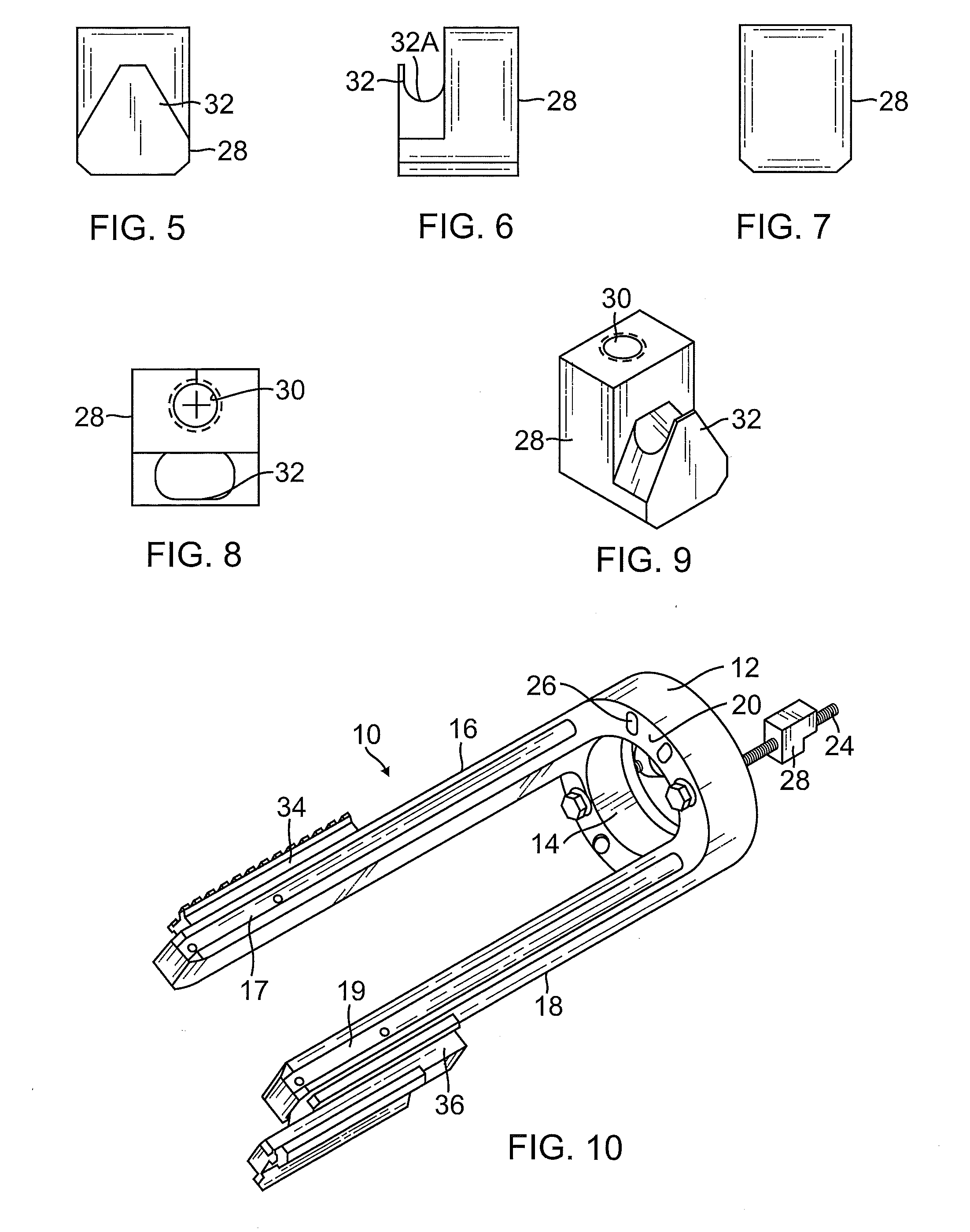
[0035]FIG. 1 is left side elevation view of an example embodiment of a heavy machine gun accessory mount 10 in accordance with the present disclosure. With reference to FIGS. 1-4, the example accessory mount comprises an annular base 12 containing a cylindrical opening or lumen 14 that is adapted to be disposed concentrically about the barrel 110 and barrel shroud 106 of a heavy machine gun 100 (see FIG. 17) on which the accessory mount 10 is to be mounted, and to permit reciprocating axial recoil of the barrel relative to the base during firing of the recoil-operated weapon.

[0036]With reference to FIG. 17, the host machine gun 100 includes a receiver 102 that is typically mounted on a stand 104 of a type that enables a barrel 110 of the gun to be traversed left and right and elevated up and down. The gun 100 further includes a shroud 106 that includes a bushing 106A having a substantially planar front surface 106B, and incorporates a plurality of generally circular holes 108 dispos...


PUM


Abstract

A universal accessory mount for a heavy machine gun includes an annular base adapted to be disposed concentrically over a front end of a shroud of the gun and having diametrically opposing upper and lower accessory mounting tines extending forwardly therefrom. A holding mechanism pulls a planar floor of a counterbore in the rear of the base into contact with a planar front surface of the shroud of the gun. The holding mechanism includes a pair of threaded bolts extending rearwardly from the base through respective ones of a pair of diametrically opposing bolt apertures contained in the base, and a pair of cleats, each having an opening into which a rear end portion of a respective one of the bolts is received and a respective hook adapted to grip the shroud of the gun through a respective hole in the shroud.

Description

BACKGROUND[0001]1. Technical Field[0002]This disclosure relates to combat weaponry in general, and in particular, to accessory mounting devices for heavy machine guns.[0003]2. Related Art[0004]One of the more effective infantry combat weapons deployed by the United States and allied forces during both this and the last century has been the Browning .50 caliber M2HB heavy machine gun. It has been shown to be effective against infantry, lightly armored land vehicles and boats, light fortifications, and low-flying aircraft, and has been used extensively both as a vehicle-mounted weapon and for aircraft armament by the United States from 1927 to the present. It was used extensively during World War II, the Korean War, the Vietnam War and the war in Iraq. It is the primary heavy machine gun of NATO countries, and has also been used by many other countries. It is still in use today, with some modern innovations and improvements, and has been in use longer than any other small arm currentl...

Claims


Application Information

Patent Timeline
IPC IPC(8): F41C27/00F41C27/04F41G1/387
CPCF41G11/001F41H5/12F41G11/003
Inventor LAFRANCE, TIMOTHY F.PICCIOTTA, MICHAEL D.
Owner SUREFIRE LLC
Learn More