Hydraulic Unloading Valve

Inactive Publication Date: 2010-06-24
WEIR SPM
View PDF26 Cites 57 Cited by
  • Summary
  • Abstract
  • Description
  • Claims
  • Application Information

AI Technical Summary

Benefits of technology

[0005]Disclosed herein is an example of a method of relieving pressure from a pumping circuit that includes providing a relief valve that has a body, an axial passage in the body, a discharge port formed in the body in fluid communication with a portion of the passage, and a piston axially moveable within the passage and having a high pressure end a low pressure end on a side opposite the high pressure end. The method of, this example may further include providing fluid communication between the pumping circuit and the high pressure end of the piston, urging the piston into a closed position by maintaining a backpressure on the low pressure side of the piston so that the high pressure side of the piston seats into a closed position to block fluid communication between the pumping circuit and the discharge port, providing a selectively openable dump valve in pressure communication with the low pressure side of the piston, and opening the dump valve, when the pressure in the pumping circuit reaches a set point, by communicating to the dump valve a fraction of the pumping circuit pressure, so that the backpressure on the piston vents through the dump valve, the pumping circuit pressure unseats the piston, and fluid in the pumping circuit flows into the relief valve and out the discharge port.
[0006]Also disclosed herein is a pressure relief system for use with a pumping circuit. In one example the pressure relief system includes a relief valve, a body, an axial passage in the body, a discharge port formed in the body in fluid communication with a portion of the

Problems solved by technology

Pressure within the pump discharge circuit may unexpectedly inc

Method used


Image

  • Hydraulic Unloading Valve
  • Hydraulic Unloading Valve
  • Hydraulic Unloading Valve

Examples


Embodiment Construction

[0015]The method and system of the present disclosure will now be described more fully hereinafter with reference to the accompanying drawings in which embodiments are shown. The described method and system may be in many different forms and should not be construed as limited to the illustrated embodiments set forth herein; rather, these embodiments are provided so that this disclosure will be thorough and complete, and will fully convey its scope to those skilled in the art. Like numbers refer to like elements throughout.

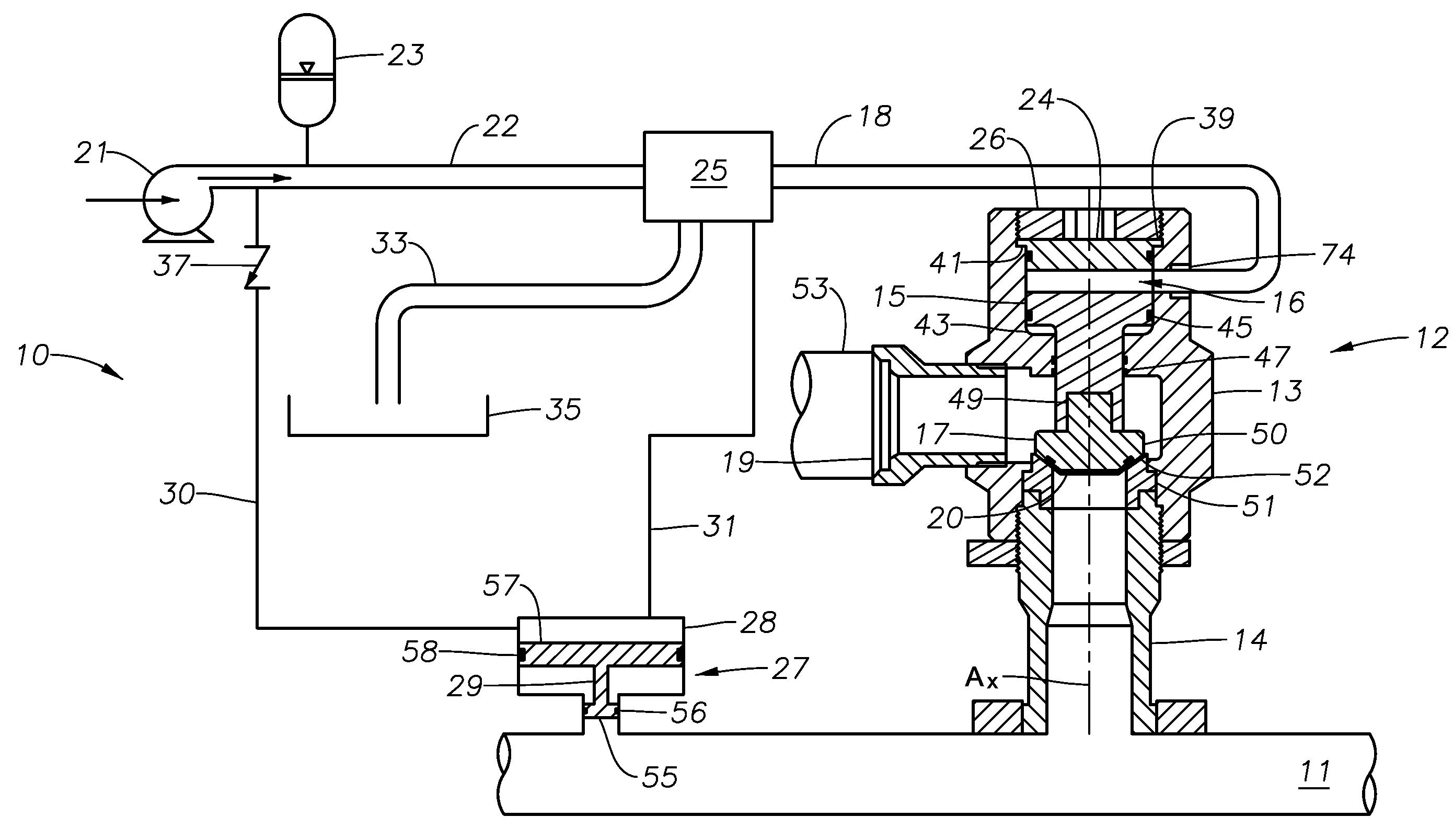
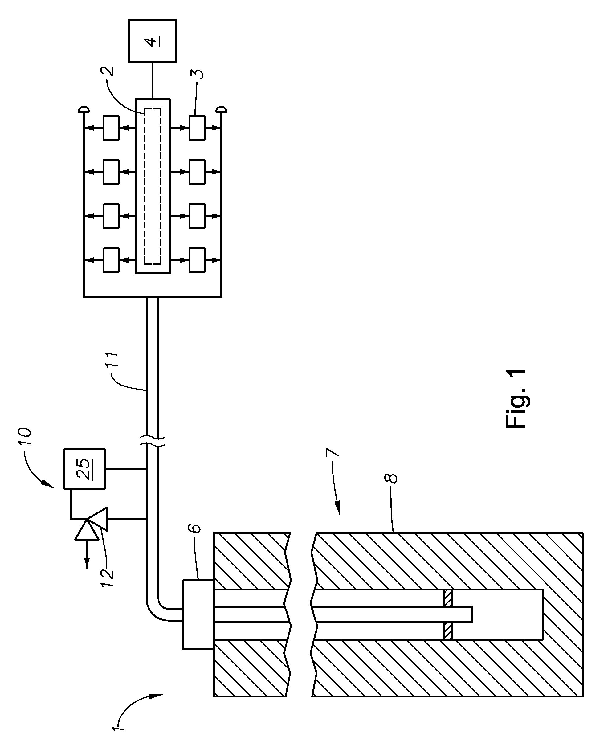
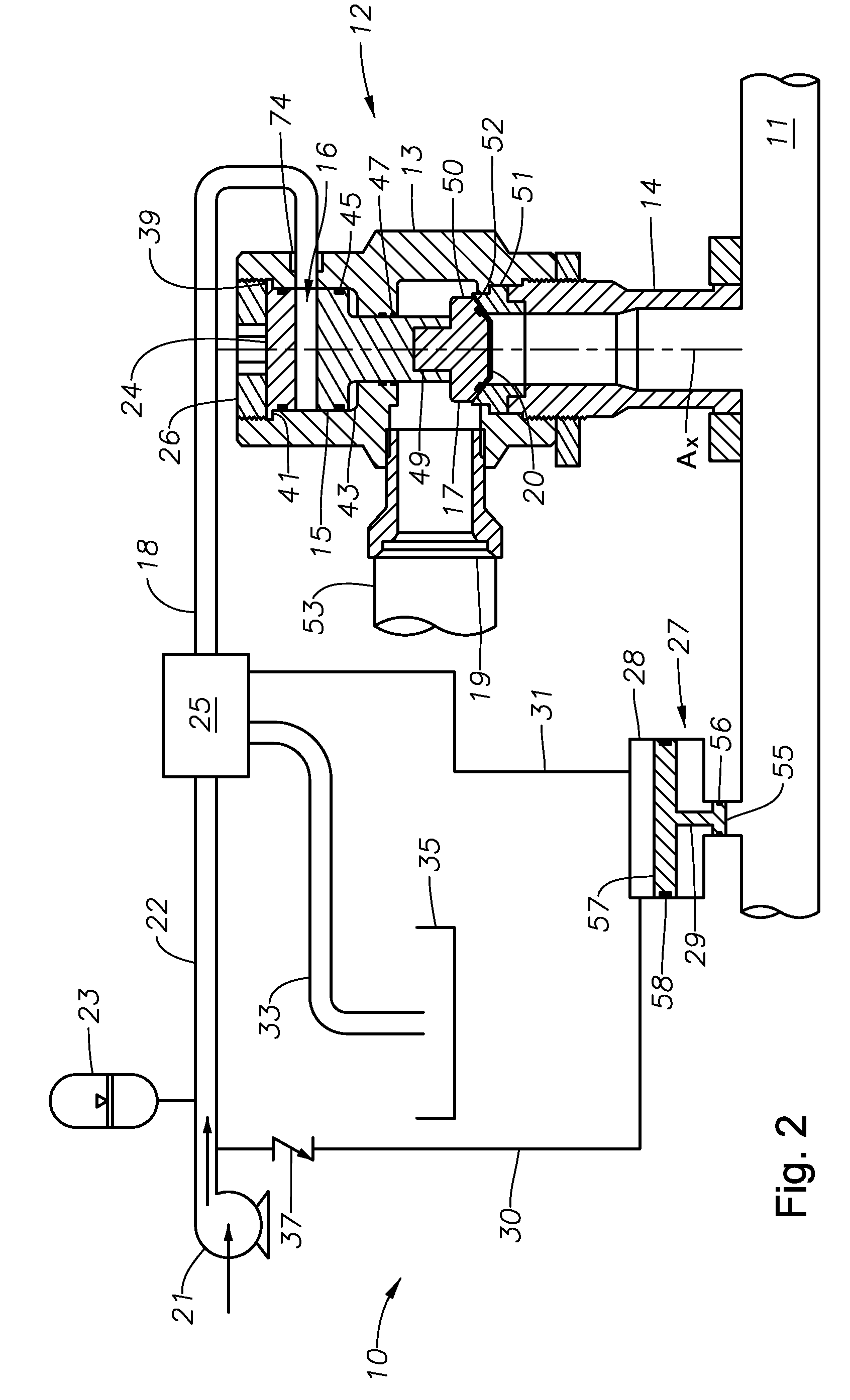
[0016]FIG. 1 is schematic partial sectional view illustrating an example of a fracing system 1 delivering high pressure fluid into a subterranean formation. Example uses of the fluid include fracturing a formation, treating the well, or cementing casing. The system 1 includes a manifold 2 connected to pumps 3 that pressurize fluid for delivery to the subterranean formation. The pumps 3 each have a suction line shown drawing a fluid from a reservoir 4. The reservoir...


PUM


Abstract

A pressure relief system for a reciprocating pumping system that deintensifies pressure from the pumping system and controls relief operation with the deintensified pressure. The relief system includes a relief valve connected to the pumping system and a control system that selectively opens the relief valve when an overpressure is sensed in the pumping system. To keep the relief valve in a closed position, the control system maintains a backpressure on the relief valve using the deintensified pressure. A dump valve in the control system selectively vents the backpressure so the relief valve can open. A charging system can be used for charging the control system and for reseating the relief valve.

Description

CROSS REFERENCE TO RELATED APPLICATIONS[0001]This application claims priority to and the benefit of co-pending U.S. Provisional Application Ser. No. 61 / 138,795, filed Dec. 18, 2008, the full disclosure of which is hereby incorporated by reference herein.FIELD OF THE INVENTION[0002]The present invention relates in general to valves and in particular to an improved pressure relief valve that relieves a pressure of a system. The relieving set pressure is maintained by a dedicated hydraulic circuit.DESCRIPTION OF RELATED ART[0003]In oil field operations, reciprocating pumps are often used for various purposes. Some reciprocating pumps, generally known as “service pumps,” typically pump service fluids used for downhole operations such as cementing, acidizing, or fracing a well. These service pumps may typically operate for relatively short periods of time, but on a frequent basis such as several times a week. Often they are mounted to a truck or a skid for transport to various well sites...

Claims


Application Information

Patent Timeline
IPC IPC(8): F16K15/02
CPCF16K17/10Y10T137/7904Y10T137/0396
Inventor KOTAPISH, EDWARD C.MATZNER, MARK D.
Owner WEIR SPM
Why Eureka
Try Eureka