
Method and apparatus for reconstructing 3D model

reconstruction technology, applied in the field of reconstruction and rendering a real-time 3d model, can solve the problems of increasing computational load and increasing computational load for improving accuracy, and achieve the effect of efficient compensation, reduced computational time and improved model accuracy

Inactive Publication Date: 2010-06-24
ELECTRONICS & TELECOMM RES INST
View PDF7 Cites 51 Cited by
  • Summary
  • Abstract
  • Description
  • Claims
  • Application Information

AI Technical Summary

Benefits of technology

[0011]It is, therefore, a primary object of the present invention to provide a method capable of reducing the computational time of reconstructing a 3D model, in such a way as to extract silhouette information from images captured by a number of cameras, divide a 3D space into voxels and project the center point of each voxel onto an image plane.
[0012]Another object of the present invention is to provide a method capable of improving the accuracy of a reconstructed 3D model by converting a voxel model into a mesh structure and performing view-dependent texturing using images captured from a number of viewpoints.
[0022]It is preferable that the mesh model conversion unit compensates for a loss of outer information resulting from using a coordinate of the center point of voxel with reference to the silhouette information of the multi-viewpoint image when determining an outer mesh.
[0023]In accordance with the present invention, the 3D information of a person or an object can be acquired using several cameras, and an image can be generated from a new viewpoint. Accordingly, real-time processing is possible because these processes can use the parallel processing function of a GPU. Furthermore, in accordance with the present invention, whether an object region is included, can be determined on the basis of the center point of a voxel cube, and outer information that may be lost is efficiently compensated for at the mesh conversion step. Accordingly, the computational time can be reduced and the accuracy of a model can be improved.

Problems solved by technology

Accordingly, the computational load for improving accuracy is greatly increased.
If this calculation is performed on all voxels included in the 3D reconstruction space, the computational load is greatly increased.

Method used


Image

  • Method and apparatus for reconstructing 3D model
  • Method and apparatus for reconstructing 3D model
  • Method and apparatus for reconstructing 3D model

Examples


Embodiment Construction

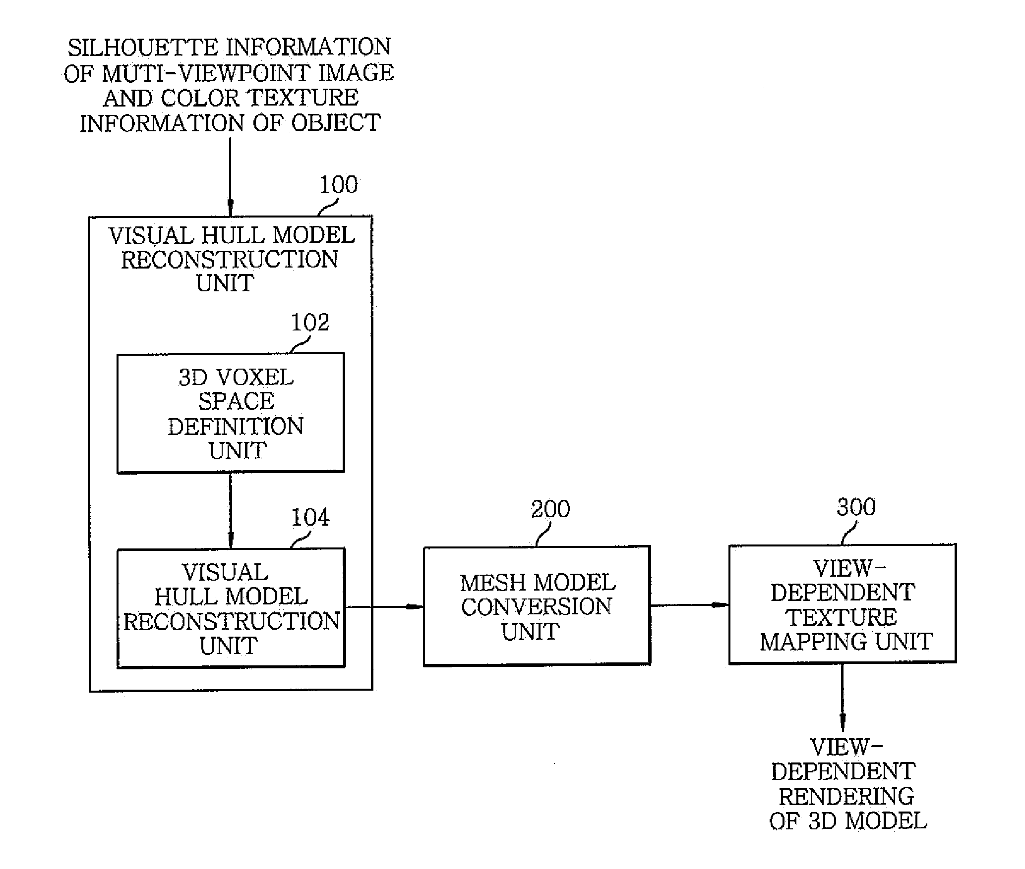
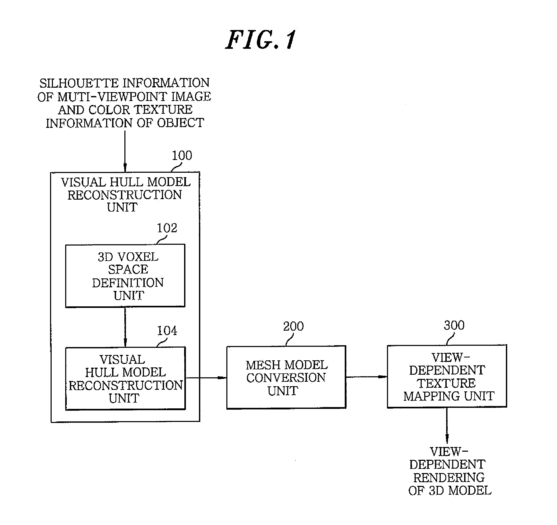
[0027]In accordance with the present invention, 3D information of an object captured by a number of cameras or a multi view camera is reconstructed in real time, and model structure conversion and view-dependent rendering are performed to achieve realistic 3D model rendering.

[0028]The computational load can be greatly reduced through the back-projection of a center point of a voxel other than the eight vertexes of a voxel, and the loss of outer voxels that may occur at this time can be compensated by referring to silhouettes of input images in a mesh conversion process.

[0029]In order to render a realistic model, a method of selecting an optimal input image which is referred to as a texture of each vertex of triangular meshes constituting the model and taking the depth of a vertex into consideration upon texturing so as to determine the portions of the model which are partially hidden due to a change in the viewpoint is provided.

[0030]Embodiments of the present invention will be desc...


PUM


Abstract

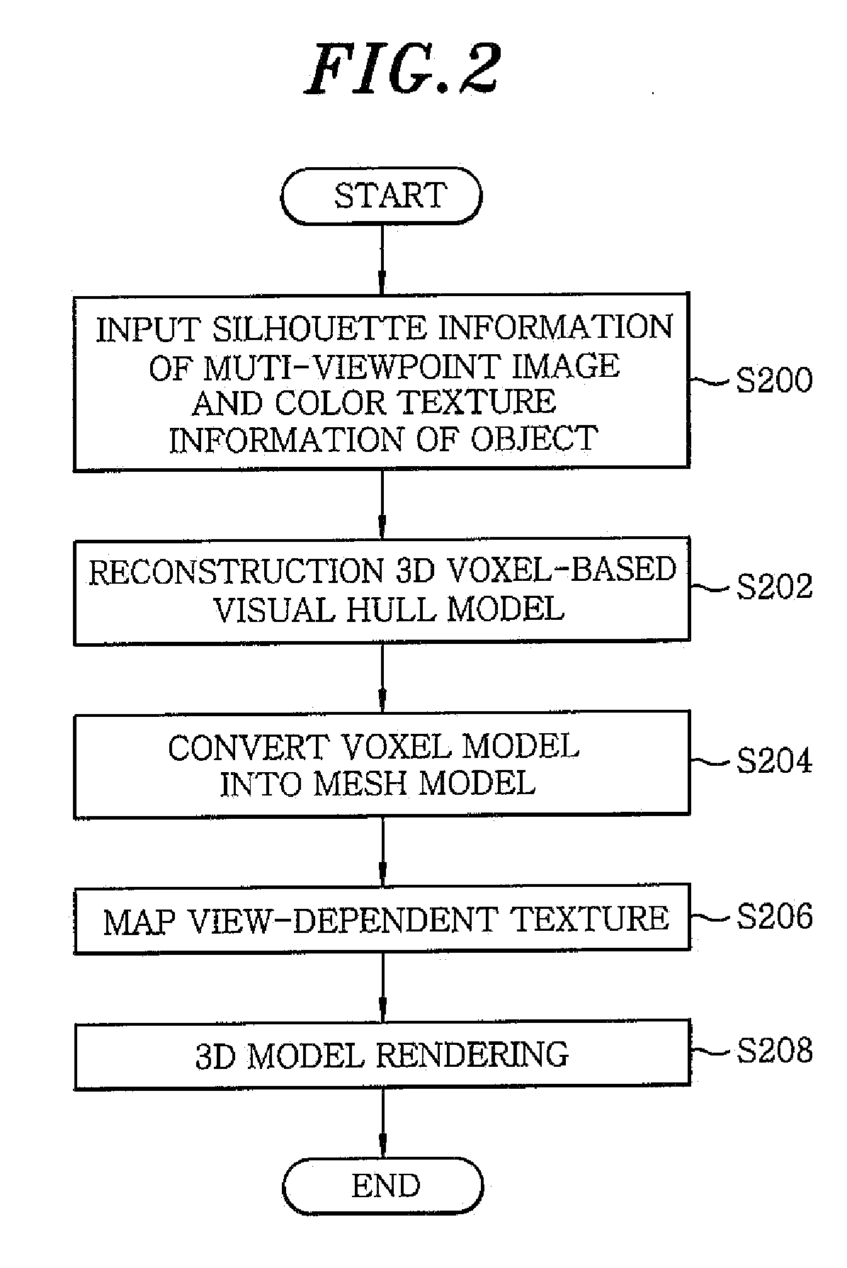
A method of reconstructing a 3D model includes reconstructing a 3D voxel-based visual hull model using input images of an object captured by a multi view camera; converting the 3D voxel-based visual hull model into a mesh model; and generating a result of view-dependent rendering of a 3D model by performing the view-dependent texture mapping on the mesh model obtained through the conversion. Further, the reconstructing includes defining a 3D voxel space to be reconstructed; and excluding voxels not belonging to the object from the defined 3D voxel space.

Description

CROSS-REFERENCE(S) TO RELATED APPLICATIONS[0001]The present invention claims priority of Korean Patent Application No. 10-2008-0131767, filed on Dec. 22, 2008, which is incorporated herein by reference.FIELD OF THE INVENTION [0002]The present invention relates to a method of reconstructing and rendering a real-time 3D model; and, more particularly, to a three-dimensional (3D) model reconstruction technology suitable to reconstruct 3D information using the two-dimensional (2D) silhouette information of images, captured from a number of viewpoints and to generate an image from a new viewpoint in real time.BACKGROUND OF THE INVENTION [0003]A visual hull reconstruction scheme is well known as a method of reconstructing a 3D model having a voxel (volume+pixel) structure from a silhouette image.[0004]A size of a 3D space to be reconstructed is determined, the entire space is divided into voxels having cubic form, and eight corners constituting each voxel are back-projected onto a silhouet...

Claims


Application Information

Patent Timeline
Patent Type & Authority Applications(United States)
IPC IPC(8): G06T17/00
CPCG06T15/205G06T15/00G06T17/00
Inventor PARK, JI YOUNGPARK, IL KYUKIM, HO WONKIM, JIN SEOLEE, JI HYUNGLEE, SEUNG WOOKCHU, CHANG WOOLIM, SEONG JAEHWANG, BON WOOKOO, BON KILEE, GIL HAENG
Owner ELECTRONICS & TELECOMM RES INST
Learn More