Method and system for improved copy quality in a multifunction reprographic system

a reprographic system and multi-function technology, applied in the field of multi-function reprographic systems, can solve the problems of smearing sharp edges in original documents, cost constraints and performance limits of the devices or software that comprise the image path, and the image path is usually one of the more complex and costly components of such digital multi-function devices, so as to achieve the effect of maximizing the image quality of outpu

Inactive Publication Date: 2010-06-24
XEROX CORP
View PDF74 Cites 2 Cited by
  • Summary
  • Abstract
  • Description
  • Claims
  • Application Information

AI Technical Summary

Benefits of technology

[0007]Conventional image path electronics may also utilize binary image paths. In this situation, if the input information is scanned in a binary manner at sufficiently high resolution, the scanned image can be reconstructed at the output with little or no perceptible loss of image quality.
[0015]Therefore, it is desirable to implement a method of reconstructing a contone image from its halftoned counterpart that is efficient in use of image path resources and at the same time is adaptive to the different characteristics of the underlying image so as to maximize the image quality of the output.

Problems solved by technology

The image path is usually one of the more complex and costly components of such digital multifunction devices.
On the other hand, there are cost constraints and performance limits on the devices or software that comprise the image path.
While such a system does an adequate job of converting the high resolution binary data to analog data, these solutions also have the deleterious effect of smearing sharp edges in the original document.
Such an effect is particularly detrimental when reproducing text and line art.
However, such systems are subject to problems.
One such problem is the need to somehow distinguish those parts of the image that have edges from those parts of the image that do not.

Method used


Image

  • Method and system for improved copy quality in a multifunction reprographic system
  • Method and system for improved copy quality in a multifunction reprographic system
  • Method and system for improved copy quality in a multifunction reprographic system

Examples


Embodiment Construction

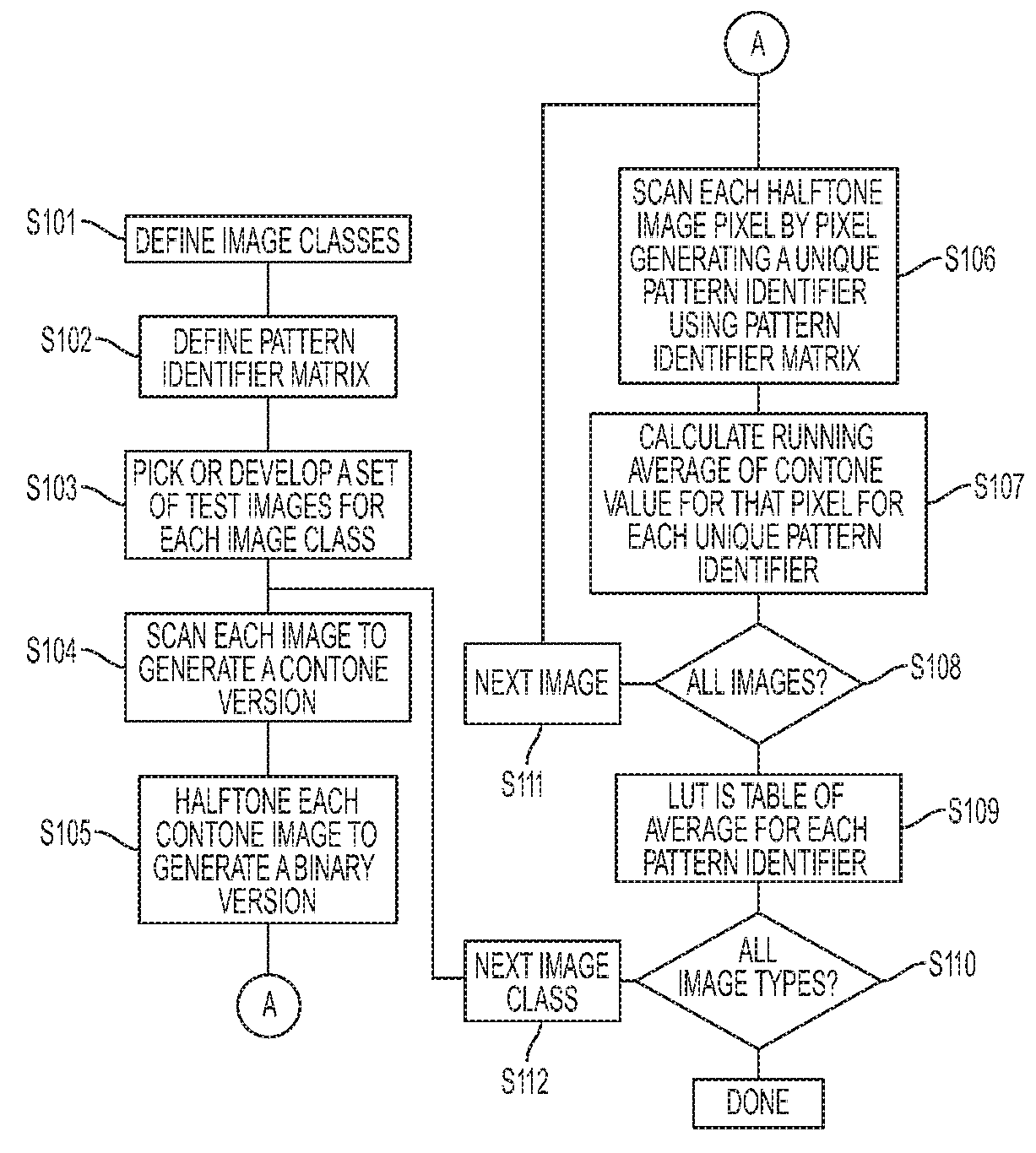
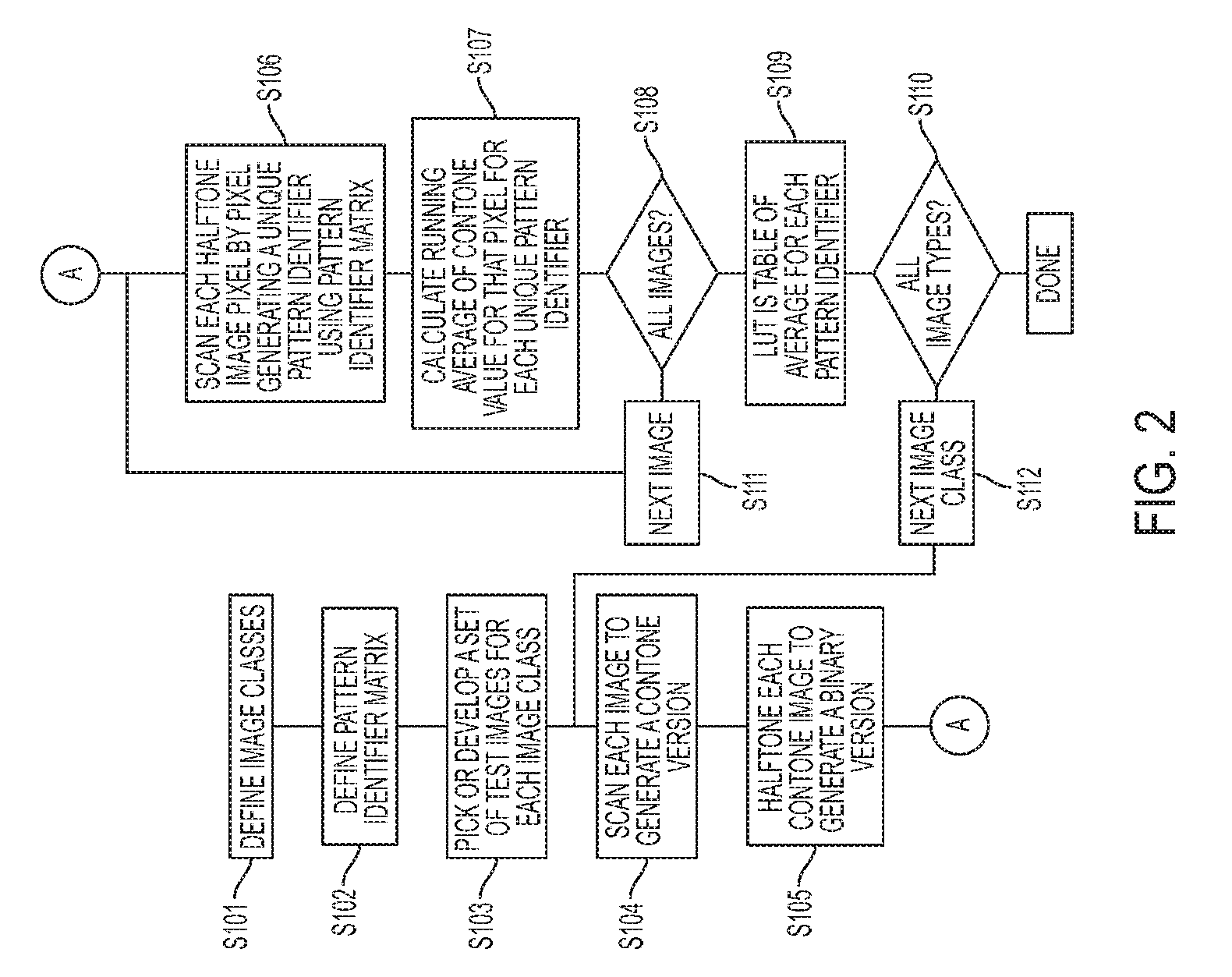
[0022]For a general understanding, reference is made to the drawings. In the drawings, like references have been used throughout to designate identical or equivalent elements. It is also noted that the drawings may not have been drawn to scale and that certain regions may have been purposely drawn disproportionately so that the features and concepts could be properly illustrated.

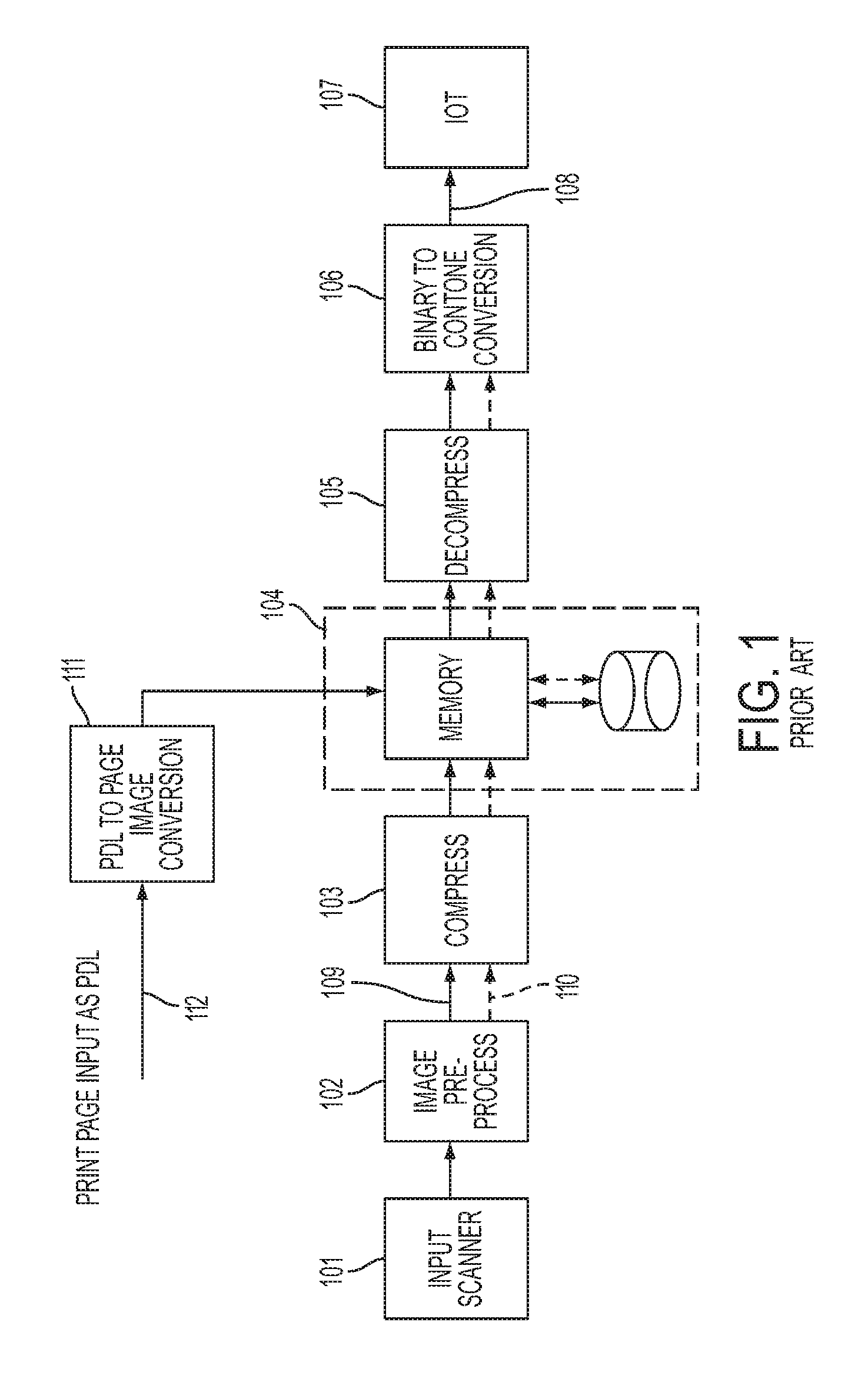
[0023]FIG. 1 shows, in schematic form the general, image path of a multifunction reprographic system. The image path is a combination of hardware and software elements that generate, process, and store the digital page images. A control system (not shown) configures each element of the image path depending on the user job. The control system also schedules the various jobs and functions of the entire system.

[0024]As illustrated in FIG. 1, digital scanner 101 accepts a hardcopy version of the page or pages to be copied and converts each page to a digital image, in contone form, at some moderately high resolut...


PUM


Abstract

A method and system reconstructs a contone image from a binary image by first tagging pixels to identify one of a multiplicity of image content types. The tag information and the pattern of bits surrounding the pixel to be converted to a contone value are used to reconstruct a contone image from a binary image. The pattern of bits in the neighborhood is used to generate a unique identifier. The unique identifier is used as the address for a lookup table with the contone value to be used wherein each lookup table corresponds to an image context type.

Description

PRIORITY INFORMATION[0001]This application is a divisional application of co-pending U.S. patent application Ser. No. 11 / 272,182, filed on Nov. 10, 2005. This application claims priority, under 35 U.S.C. §120, from co-pending U.S. patent application Ser. No. 11 / 272,182, filed on Nov. 10, 2005. The entire content of co-pending U.S. patent application Ser. No. 11 / 272,182, filed on Nov. 10, 2005 is hereby incorporated by reference.BACKGROUND AND SUMMARY[0002]Digital multifunction reprographic systems are well known and have replaced optical reprographic systems as a way to reproduce images. In these conventional digital multifunction reprographic systems, a scanner accepts a document to be copied and converts the document into electronic image(s). These images, usually in the form of pages, are then passed to a central control unit which may re-order or reorganize these pages and then, depending on the request of the user of the device, send the pages or images to a destination. Often ...

Claims


Application Information

Patent Timeline
Patent Type & Authority Applications(United States)
IPC IPC(8): G06K15/02
CPCH04N1/40075
Inventor NAGARAJAN, RAMESHTSE, FRANCIS KAPOLEE, CHIA-HAOCASSIDY, JOHN CHRISTOPHERWU, JOHN W.
Owner XEROX CORP
Why Eureka
Try Eureka