
Multiple antenna wireless telecommunication method and system

a wireless telecommunication and multi-antenna technology, applied in diversity/multi-antenna systems, multi-frequency code systems, transmission path sub-channel allocation, etc., can solve the problem of not being able to extend cell coverage at all, unable to apply stc matrix a to these maps messages, and the wimax standard and profiles are precluded

Inactive Publication Date: 2010-06-24
QUALCOMM INC
View PDF10 Cites 92 Cited by
  • Summary
  • Abstract
  • Description
  • Claims
  • Application Information

AI Technical Summary

Problems solved by technology

Although provisions were made in the 802.16e mobile WiMAX standard to enable the aforementioned approaches when transmitting the individual DL traffic, the possibilities are much more limited for achieving a comparable performance boost when transmitting broadcast DL and UL (Up Link) maps messages.
While the adaptive ‘narrow’ beam forming techniques, per definition, cannot provide simultaneous coverage across the entire sector when a broadcast message is transmitted, applying STC Matrix A to these maps messages is precluded by the WiMAX standard and profiles.
Thus, even when the individual data connection's range can be extended using the MIMO techniques, the cell coverage won't be extended at all due to the limited coverage during transmission of the maps zone.
One common approach to overcome this bottleneck is using a stronger FEC (Forward Error Correction) (with repetition coding), at the immediate expense of capacity, due to greater overhead of map messages.
CDD is widely recognized to perform well in rich fading environments, but raises many issues in line-of-sight (LOS) or near line-of-sight situations, since it can create interference.
Performance degradation due the interference can be reduced by advertising the CDD to the receiver, i.e., signaling to the subscriber explicitly with a dedicated message describing how the CDD scheme is applied in the DL transmitter, with an additional overhead of this signaling, but at the expense of the useful bandwidth.
One additional aspect of using either CDD or STC Matrix A techniques is that, while both are well defined for the two transmit antennae case, it could be very challenging to extend their usage beyond this number of transmit antennae available in the base station.

Method used


Image

  • Multiple antenna wireless telecommunication method and system
  • Multiple antenna wireless telecommunication method and system
  • Multiple antenna wireless telecommunication method and system

Examples


Embodiment Construction

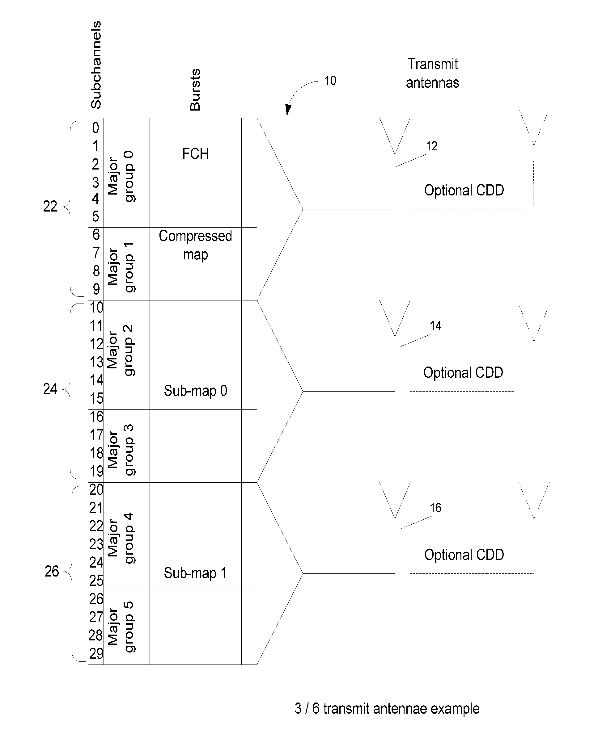
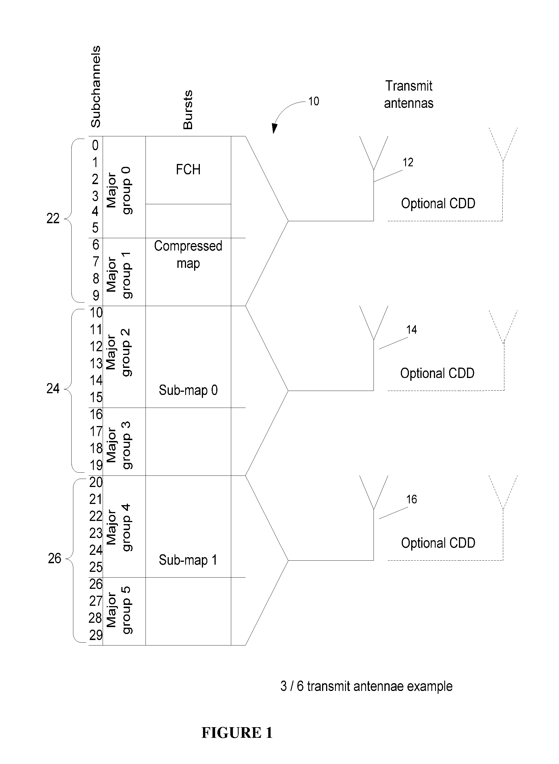
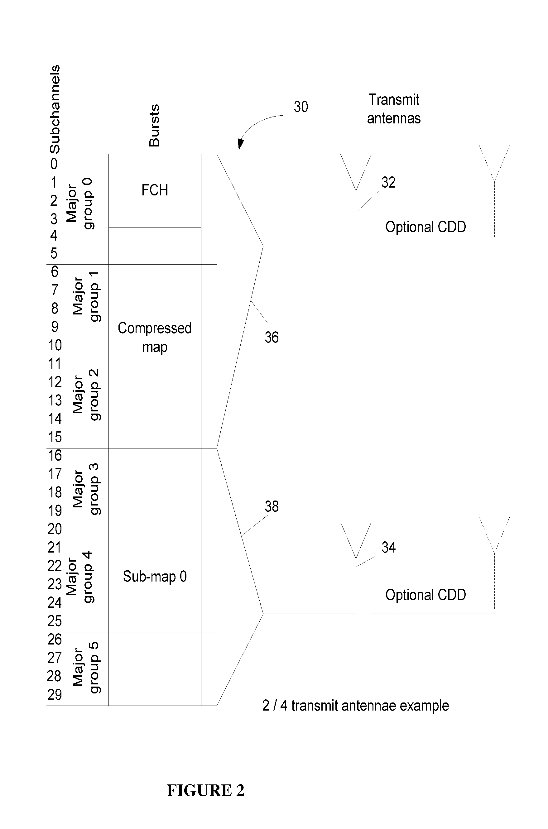
[0016]The present invention relates to a method and system for wireless telecommunication providing expanded capacity and / or coverage for DL and UL maps messages and other portions of transmitted traffic, when using multiple antennae. This is accomplished by providing Downlink Switched Sub-channels Diversity—DSSD during transmission.

[0017]The DSSD is a novel scheme where the entire spectrum of the transmitted signal is split to individual sub-channels or groups of sub-channels, each of which is then appropriately boosted, preferably by a factor which is an inverse of the ratio of the group's aggregate bandwidth (BW) to the whole available BW. According to some embodiments, given a complex modulated subcarrier s, to undergo power boosting of factor P, the corresponding boosted subcarrier S is obtained by multiplying s with the gain G=sqrt(P), i.e. S=Gs. For example, in the simplest case of the 2-fold, described below with reference to FIG. 2, the 1st group contains 16 sub-channels wh...


PUM


Abstract

A wireless telecommunication system and method including at least two transmit antennae and means for implementing a downlink switched sub-channels diversity scheme during transmission. The method includes splitting a total bandwidth allocated for transmission of a transmitted signal to individual sub-channels or groups of sub-channels; boosting each of the sub-channels or groups of sub-channels; and routing each of the sub-channels or groups of sub-channels to a different transmit antenna.

Description

RELATED APPLICATIONS[0001]This application claims the benefit of U.S. provisional application Ser. No. 61 / 138,535 filed 18 Dec. 2008.FIELD OF THE INVENTION[0002]The present invention relates to wireless telecommunications systems, in general and, in particular, to a method and system for transmitting over a wireless OFDM (Orthogonal Frequency Division Multiplexing), or SC-FDMA (Single-Carrier Frequency Division Multiple Access) telecommunications system using multiple transmit antennas.BACKGROUND OF THE INVENTION[0003]In WiMAX systems, several multiple antennae transmit techniques have been adopted to deliver extended capacity and / or coverage in the DL (Down Link), with little or no cost to the mobile station. These MIMO (multiple input multiple output) techniques usually include STC (Space-Time Coding) Matrix A (aka the Alamouti scheme), which is commonly used as a means to provide diversity, and adaptive beam forming algorithms intended to focus transmitted energy on individual su...

Claims


Application Information

Patent Timeline
Patent Type & Authority Applications(United States)
IPC IPC(8): H04B7/208H04L27/28H04B7/02
CPCH04B7/0697H04L5/0044H04L5/0023
Inventor GOTMAN, MAXTOUBOUL, ASSAFBARAK, OZ
Owner QUALCOMM INC
Learn More