Method and system for performing time synchronization between nodes in wireless communication system

a wireless communication system and time synchronization technology, applied in the direction of synchronisation arrangement, network topologies, electrical appliances, etc., can solve the problems of inability to use the method, the above-described method of measuring a delay time in advance and inputting the measured delay time in the hardware during hardware manufacturing, and the inability to achieve bidirectional delay between the reference node and the correspondent node. , to achieve the effect of preventing out-of-time synchronization, preventing out-

Active Publication Date: 2010-06-24
SAMSUNG ELECTRONICS CO LTD
View PDF6 Cites 23 Cited by
  • Summary
  • Abstract
  • Description
  • Claims
  • Application Information

AI Technical Summary

Benefits of technology

[0029]Another aspect of the present invention provides a time synchronization method and system capable of preventing out-of-time synchronization, which may occur due to a hardware difference between nodes in a wireless communication system.
[0030]Another aspect of the present invention provides a time synchronization method and system capable of preventing out-of-ti

Problems solved by technology

Since the delay time must be measured by a hardware maker and then input into the hardware, this method cannot be used if the hardware does not support this function.
The first above-described method of measuring a delay time in advance and inputting the measured delay time in the hardware during hardware manufacturing cannot be used in a communication system that does not support this method, such as IEEE 802.15.4, since the hardware must support this function.
However, the bidirectional delays between the reference node and the correspondent node may not be equal.
This may not only result from a hardware difference between the reference node and the correspondent node, but may also occur, because if an interrupt occurs in a period after the reference node and the correspondent node read their current times and before packets are recorded in their hardware transmission buffers, a delay may occur to handl

Method used


Image

  • Method and system for performing time synchronization between nodes in wireless communication system
  • Method and system for performing time synchronization between nodes in wireless communication system
  • Method and system for performing time synchronization between nodes in wireless communication system

Examples


Embodiment Construction

[0042]The following description with reference to the accompanying drawings is provided to assist in a comprehensive understanding of embodiments of the invention as defined by the claims and their equivalents. It includes various specific details to assist in that understanding but these are to be regarded as mere examples. Accordingly, those of ordinary skill in the art will recognize that various changes and modifications of the embodiments described herein can be made without departing from the scope and spirit of the invention. In addition, descriptions of well-known functions and constructions are omitted for clarity and conciseness.

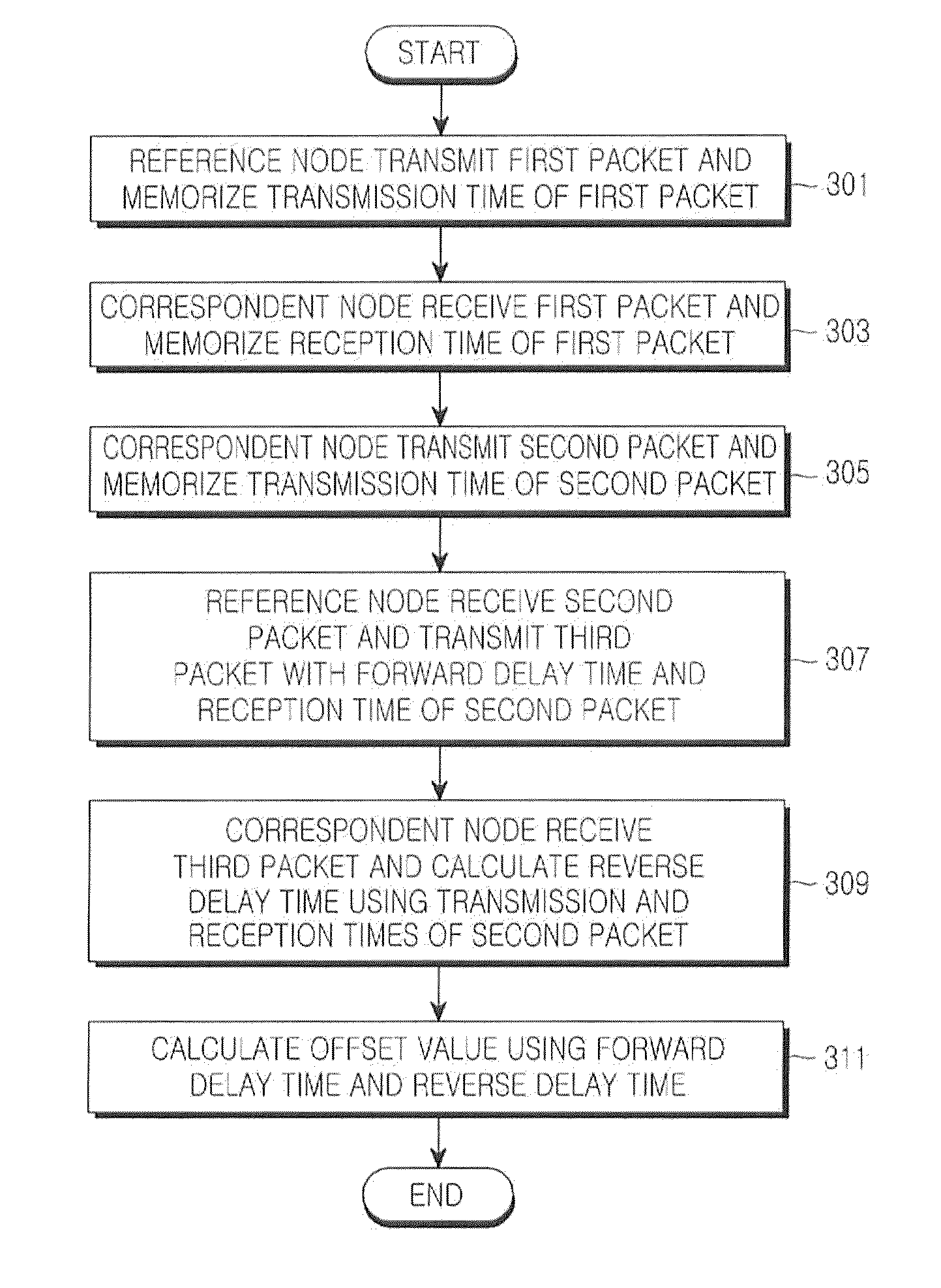
[0043]The present invention is directed to calculating a difference between a packet transmission time measured by a reference node and a packet reception time measured by a correspondent node by exchanging packets with time information included therein between nodes requiring time synchronization, i.e., the reference node (or a transmitting node) ...


PUM


Abstract

A method is provided for synchronizing time between nodes in a wireless communication system. A reference node transmits a first packet to a correspondent node. Upon receiving the first packet, the correspondent node transmits a second packet with a reception time of the first packet recorded therein, to the reference node. Upon receiving the second packet, the reference node calculates a forward delay time using a transmission time and the reception time of the first packet. The correspondent node receives a third packet with the forward delay time from the reference node, and calculates a reverse delay time. The correspondent node calculates an offset value for the synchronization using the forward delay time and the reverse delay time.

Description

PRIORITY[0001]This application claims priority under 35 U.S.C. §119(a) to a Korean Patent Application filed in the Korean Intellectual Property Office on Dec. 18, 2008 and assigned Serial No. 10-2008-0129251, the contents of which are incorporated herein by reference.BACKGROUND OF THE INVENTION[0002]1. Field of the Invention[0003]The present invention relates generally to a method and system for performing synchronization between nodes in a wireless communication system, and more particularly, to a method and system for performing time synchronization between nodes in a wireless communication system.[0004]2. Description of the Related Art[0005]Ubiquitous networking, which has recently been attracting public attention, has also been increasingly intellectual and autonomous and has created new ubiquitous services over networks, including business activity services related to production and distribution, welfare services regarding medical care and medical treatment, and environmental s...

Claims


Application Information

Patent Timeline
IPC IPC(8): H04J3/06
CPCH04W56/0015H04J3/0682H04W56/00H04W84/18
Inventor IN, JEONG-SIKCHOI, HYO-HYUNJUN, BONG-WAN
Owner SAMSUNG ELECTRONICS CO LTD
Why Eureka
Try Eureka