Image pickup apparatus and lens device

Inactive Publication Date: 2010-06-24
CANON KK
View PDF8 Cites 4 Cited by
  • Summary
  • Abstract
  • Description
  • Claims
  • Application Information

AI Technical Summary

Benefits of technology

[0021]With the arrangement of the lens device according to the second aspect of the present invention, it is possible to obtain the same advantageous effects as provided by the image pickup apparatus of the first aspect of the present invention.
[0022]Further features of the present invention will become apparent from the following description of exemplary embodiments (with reference to the attached drawings).

Problems solved by technology

However, in the above-described conventional barrier, the upper half barrier and the lower half barrier are configured to rotate about the same rotational axis, there arises the following problem: In a case where for further size reduction, the upper half barrier and the lower half barrier are each further divided in two, i.e. the barrier is comprised of four barrier blades, a rotary shaft provided at each of the left and right sides of the lens barrel requires a thickness corresponding to the four barrier blades.
Therefore, the thickness of the barrier forms an obstacle to size reduction.
Furthermore, the barrier constructed as above needs a large rotary ring for driving the upper half barrier and the lower half barrier on the front side of the lens barrel, which lowers the degree of freedom in layout, and also becomes an obstacle to size reduction.

Method used


Image

  • Image pickup apparatus and lens device
  • Image pickup apparatus and lens device
  • Image pickup apparatus and lens device

Examples


Embodiment Construction

[0051]The present invention will now be described in detail below with reference to the accompanying drawings showing an embodiment thereof. An image pickup apparatus according to the embodiment is applied to a video camera.

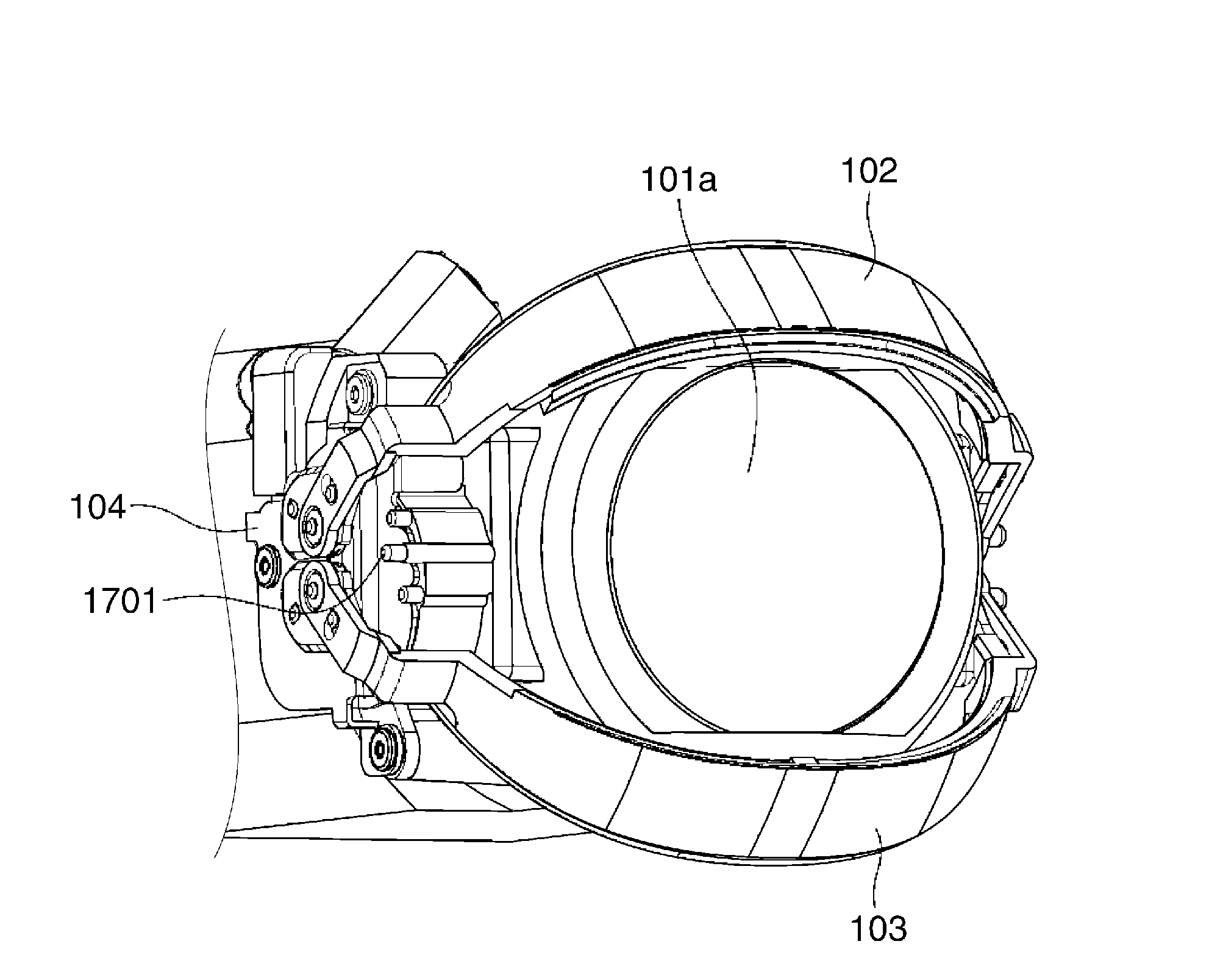
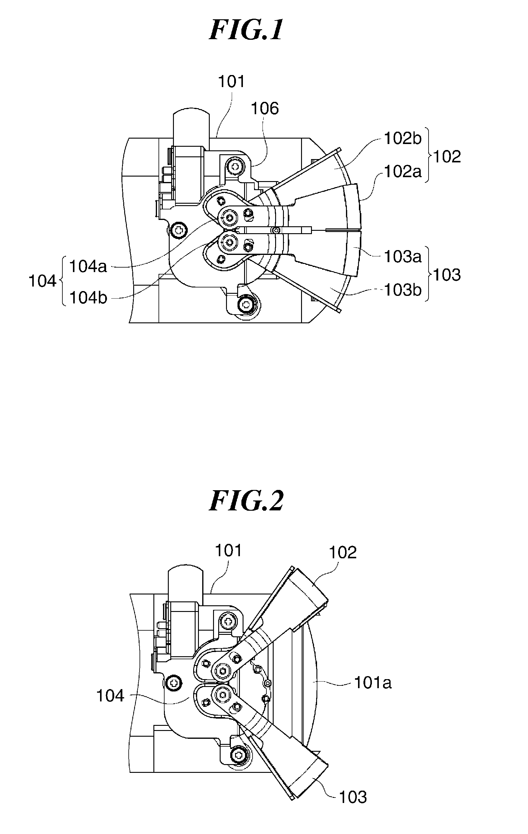
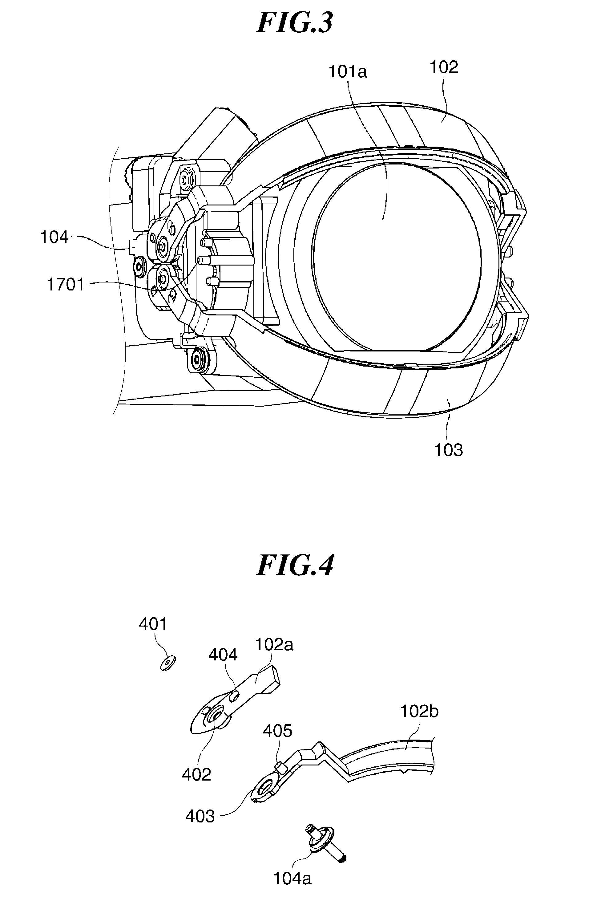
[0052]FIGS. 1 and 2 are views of essential parts of the video camera according to the embodiment of the present invention. FIGS. 1 and 2 show a lens barrel and a barrier section in side view. The lens barrel has a photographic lens provided in the front thereof. The barrier section protects the front face of the lens barrel. FIG. 1 shows a barrier closed state, while FIG. 2 shows a barrier open state. In the present embodiment, an object side of the photographic lens provided in the lens barrel 101 is defined as a front side. FIG. 3 is a perspective view of the lens barrel and the barrier section in the barrier open state of the video camera, as viewed obliquely from the front of the video camera.

[0053]In front of the photographic lens, barrier groups 102 and 103...


PUM


Abstract

An image pickup apparatus having a construction which enhances the degree of freedom in layout and enables size reduction. The image pickup apparatus includes a lens barrel, and an upper barrier group and a lower barrier group that open and close a front face of the lens barrel. The upper and lower barriers are rotated about respective upper and lower barrier rotary shafts disposed on a plane perpendicular to an optical axis of the lens barrel. A first spur gear and a second spur gear connected thereto are provided on a side of the lens barrel. A member transmits the rotation of the first spur gear driven by a motor to the lower barrier group, and another member transmits the rotation of the second spur gear to the upper barrier group.

Description

BACKGROUND OF THE INVENTION[0001]1. Field of the Invention[0002]The present invention relates to an image pickup apparatus and a lens device, which are provided with a barrier for protecting the front face of a lens barrel.[0003]2. Description of the Related Art[0004]Conventionally, there have been proposed various types of barriers each for opening / closing the front face of a camera, so as to protect a photographic lens of the camera.[0005]In image pickup apparatuses provided with barriers of the above-mentioned kind, most of the barriers have conventionally been configured to vertically or laterally open / close flat plates disposed in front of a lens barrel, as disclosed in Japanese Patent Laid-Open Publication No. 2006-98486.[0006]Further, Japanese Patent Laid-Open Publication No. 2002-258133 discloses a technique in which a barrier, which is divided into an upper part and a lower part, is opened and closed along a dome-shaped path about a point on the axis of the lens barrel.[000...

Claims


Application Information

Patent Timeline
IPC IPC(8): G03B17/00G02B23/16
CPCG03B17/00G02B23/18
Inventor FUJIWARA, YUYA
Owner CANON KK
Why Eureka
Try Eureka