Curved platform turbine blade

a technology of turbine blades and platforms, applied in the field of turbine blades, can solve the problems of increasing the heating of the platform, generating undesirable vortices, and undesirable turbulence in the flow

Inactive Publication Date: 2010-06-24
GENERAL ELECTRIC CO
View PDF22 Cites 120 Cited by
  • Summary
  • Abstract
  • Description
  • Claims
  • Application Information

AI Technical Summary

Problems solved by technology

A particular problem affecting turbine efficiency is the generation of undesirable vortices as the combustion gases are split along the airfoil leading edges near a flow boundary, such as the radially inner blade platforms.
Two horseshoe vortices flow downstream on opposite sides of each airfoil and create undesirable turbulence in the flow.
This turbulence can increase platform heating.
And, migration of the vortices radially outwardly can decrease turbine efficiency.
However, due to the complex three dimensional (3D) configuration of the turbine stages and the correspondingly complex 3D distributions of the velocity, pressure, and temperature of the combustion gases contouring of the flowpath boundaries is equally complex and is directly affected by the specific design of the specific turbine stage.
Accordingly, known flowpath contouring is highly specific to specific turbine stages and is not readily transferable to different stages whose efficiency and performance could instead be degraded.
However, due to manufacturing tolerances of the outer surfaces, adjacent platforms may not be fully flush after assembly.
The up step can cause a substantial reduction in aerodynamic performance as the combustion gas flow is locally blocked and diverted over the step onto the next adjacent platform.

Method used


Image

  • Curved platform turbine blade
  • Curved platform turbine blade
  • Curved platform turbine blade

Examples


Embodiment Construction

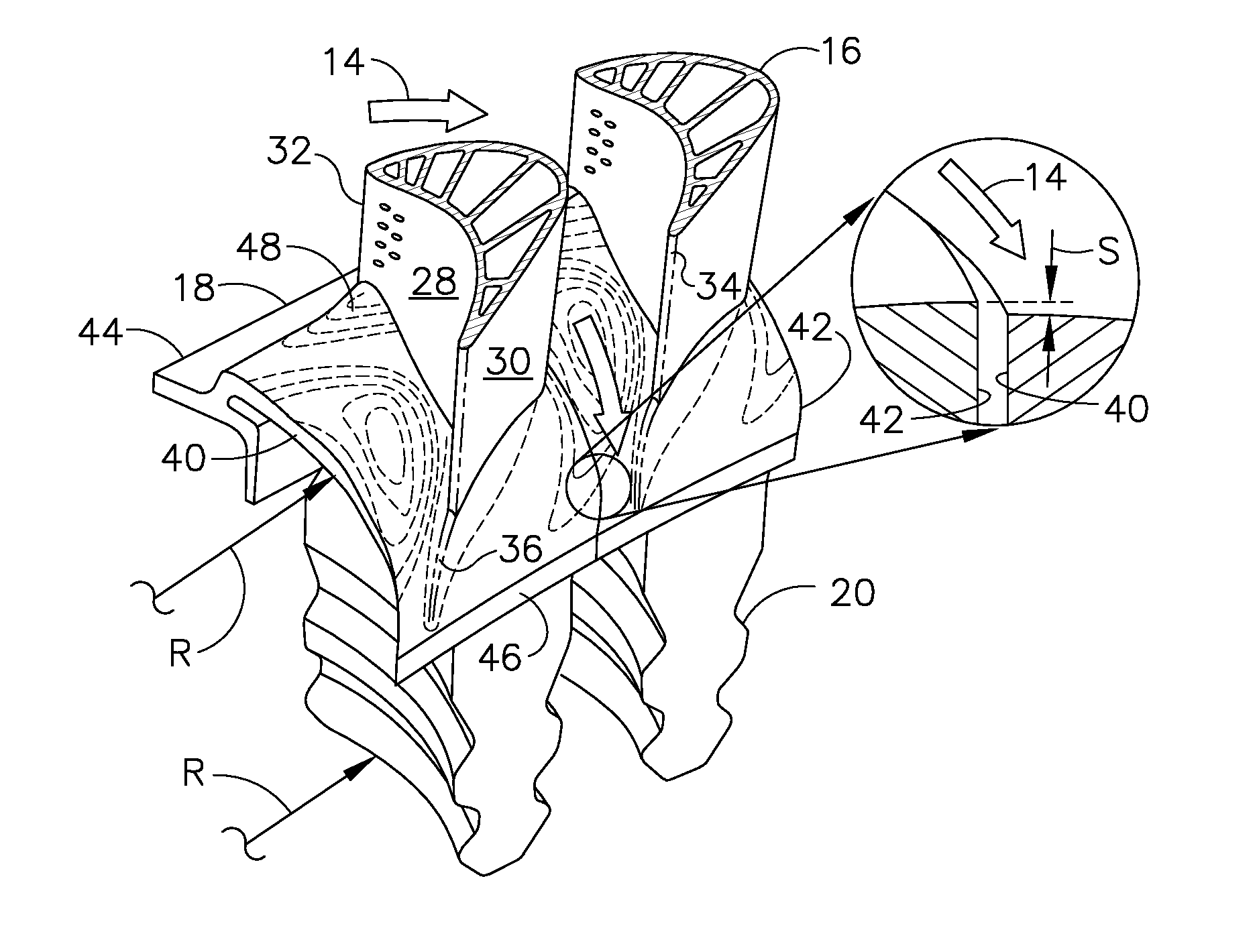
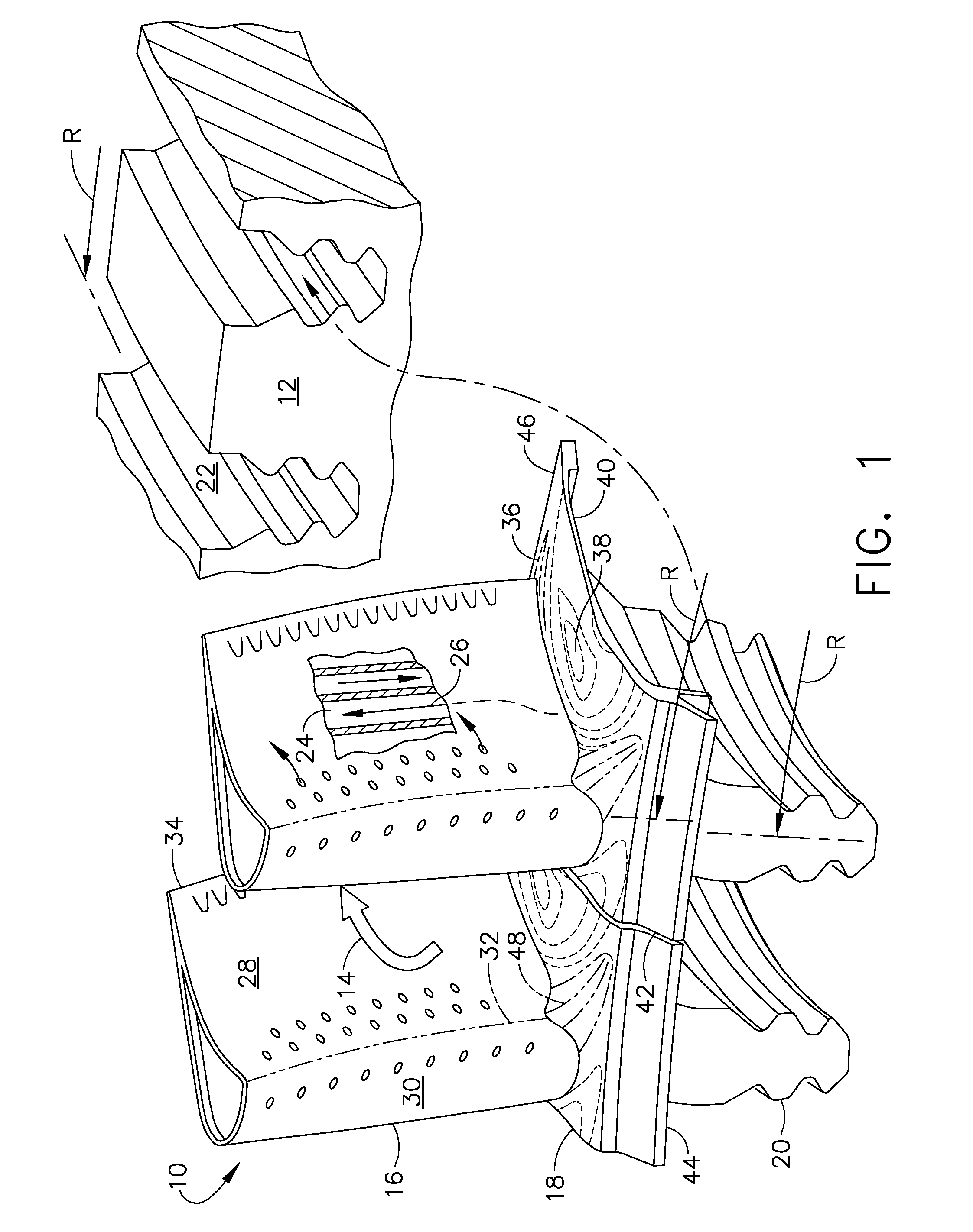
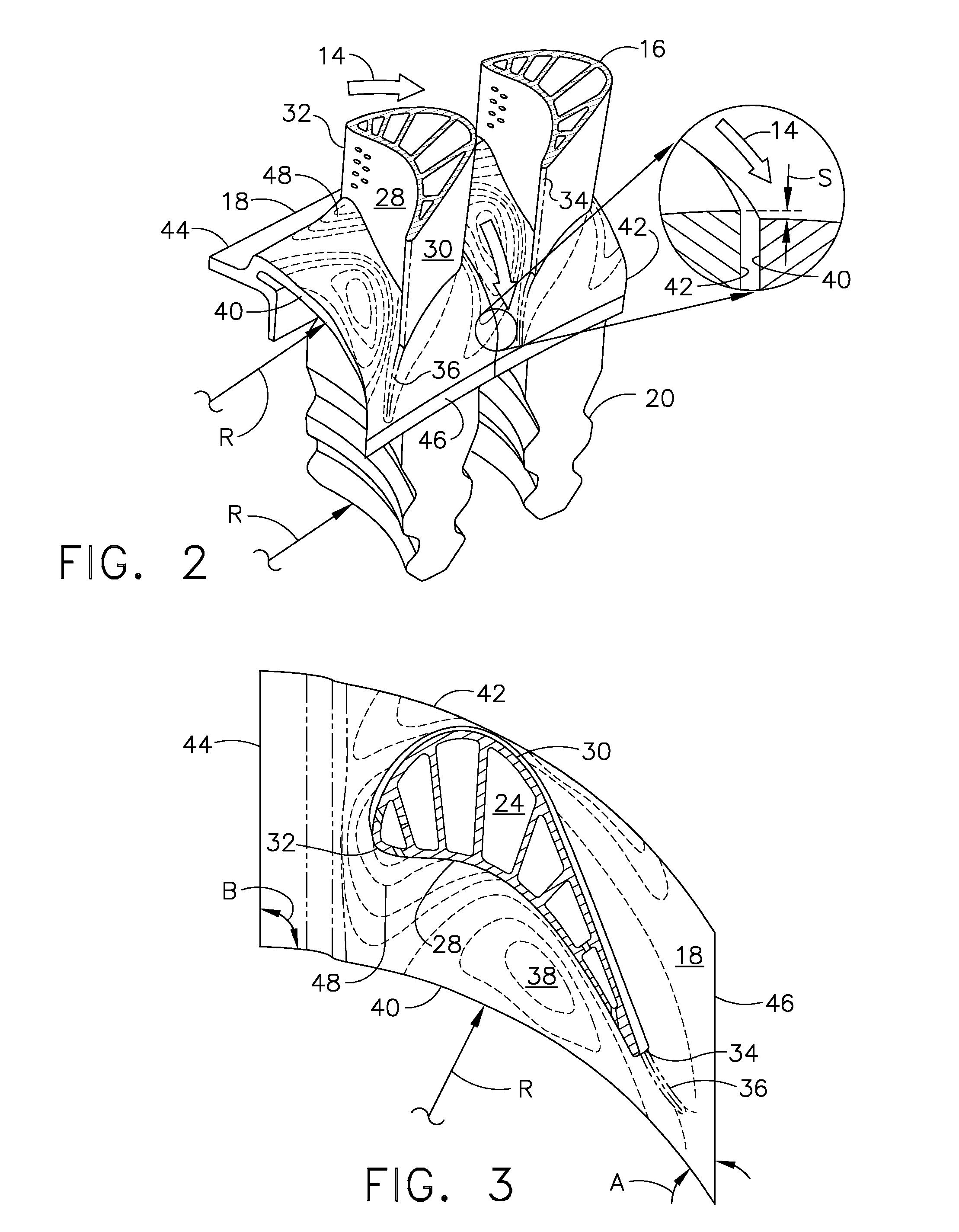
[0024]Illustrated schematically in FIG. 1 are two adjacent HPT rotor blades 10 for use in the first stage of a gas turbine engine. The blades are arranged in a common row around the perimeter of a turbine rotor disk 12, shown in part, for use in extracting energy from hot combustion gases 14.

[0025]In the engine, air is pressurized in a compressor and mixed with fuel in a combustor for generating the combustion gases 14. The combustion gases are first discharged into the HPT and then a LPT which extract energy from the combustion gases in stages.

[0026]The HPT and LPT have corresponding rotors which drive corresponding rotors in the compressor and an upstream fan in a turbofan aircraft engine application. The first stage turbine rotor blades 10 receive the hottest combustion gases from the combustor and are specifically configured in 3D for maximizing performance and turbine efficiency.

[0027]Each turbine blade 10 includes an airfoil 16 integrally joined to a platform 18 and a dovetail...


PUM


Abstract

A turbine blade includes an airfoil and integral platform at the root thereof. The platform is contoured in elevation from a ridge to a trough, and is curved axially to complement the next adjacent curved platform.

Description

BACKGROUND OF THE INVENTION[0001]The present invention relates generally to gas turbine engines, and, more specifically, to turbines therein.[0002]In a gas turbine engine, air is pressurized in a compressor and mixed with fuel in a combustor for generating hot combustion gases. Energy is extracted from the gases in turbine stages which power the compressor and a shaft that typically drives a fan in an aircraft turbofan engine application.[0003]A high pressure turbine (HPT) directly follows the combustor and receives the hottest gases therefrom from which energy is initially extracted. A low pressure turbine (LPT) follows the HPT and extracts additional energy from the gases.[0004]As energy is extracted from the gases in the various turbine stages, the velocity and pressure distributions correspondingly vary, which in turn requires correspondingly different aerodynamic profiles of the turbine stator vanes and rotor blades. The size of the vanes and blades typically increases in the d...

Claims


Application Information

Patent Timeline
Patent Type & Authority Applications(United States)
IPC IPC(8): F01D5/14
CPCF01D5/143F01D5/145F05D2240/80F05D2270/17Y02T50/673F01D5/3007Y02T50/60
Inventor PANDEY, VIDHU SHEKHARLEE, CHING-PANGSCHILLING, JAN CHRISTOPHERWADIA, ASPI RUSTOMKEITH, BRIAN DAVIDCLEMENTS, JEFFREY DONALD
Owner GENERAL ELECTRIC CO
Why Eureka
Try Eureka