Diffuser assembly for non-turbulent air flow

a diffuser and air flow technology, applied in lighting and heating apparatus, ventilation systems, heating types, etc., can solve the problems of smoke, heat and fumes migrating, and the exhaust hood cannot capture all the elements,

Inactive Publication Date: 2010-06-24
HIRSCH H HENRY
View PDF3 Cites 5 Cited by
  • Summary
  • Abstract
  • Description
  • Claims
  • Application Information

AI Technical Summary

Benefits of technology

[0006]The invention resolves the issue of turbulence and dispersion of delivered air. It causes the flow of supplied air to be smooth, evenly distributed, and perpendicular to the face of the diffuser. A specific problem the invention solves is the cross ventilation that occurs when louvered or deflector controlled air flow bounces off walls, beams and other surfaces. For example, this air movement particularly affects an open flame or heated cooking surface where the fumes should rise vertically by convection from the heated area into an exhaust hood directly above the heated surface. Any cross ventilation diverts the smoke, fumes and heat producing convection currents, even with an exhaust fan in the hood, such that the capture of these products by the exhaust hood is disturbed, preventing the exhaust hood from capturing all the elements.
[0007]Simply increasing the air flow in the exhaust hood causes increased air turbulence in the space around the exhaust hood and does not significantly increase the amount of emissions collected by the exhaust hood. In addition, increasing the flow in the exhaust hood, requires additional make-up air and a subsequent increase in A / C and / or ventilation capacity, but still does not solve the problem of smoke, heat and fumes migrating into the space around the exhaust hood. Providing a non-turbulent air flow, in proximity of the exhaust hood, eliminates the cross ventilation issues caused by current make-up air supply diffusers.

Problems solved by technology

Any cross ventilation diverts the smoke, fumes and heat producing convection currents, even with an exhaust fan in the hood, such that the capture of these products by the exhaust hood is disturbed, preventing the exhaust hood from capturing all the elements.
In addition, increasing the flow in the exhaust hood, requires additional make-up air and a subsequent increase in A / C and / or ventilation capacity, but still does not solve the problem of smoke, heat and fumes migrating into the space around the exhaust hood.

Method used


Image

  • Diffuser assembly for non-turbulent air flow
  • Diffuser assembly for non-turbulent air flow
  • Diffuser assembly for non-turbulent air flow

Examples


Embodiment Construction

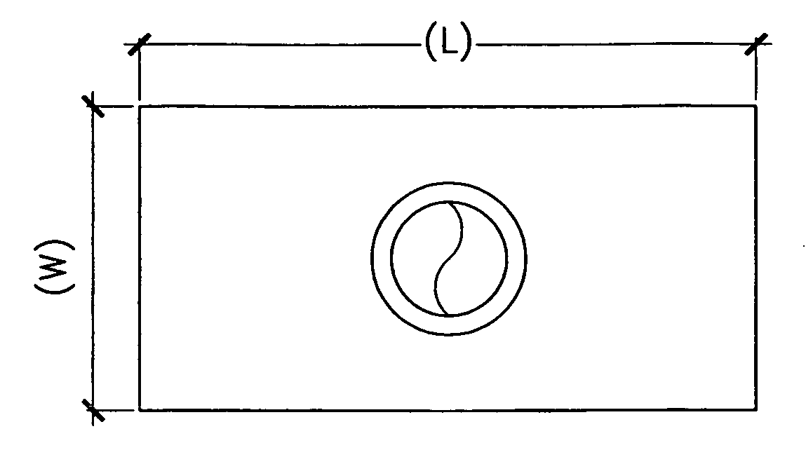
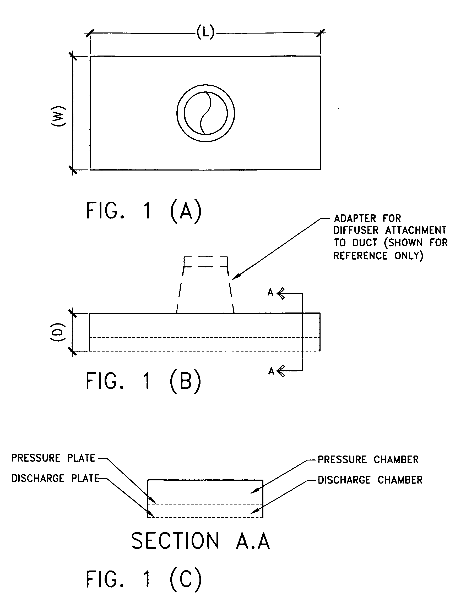
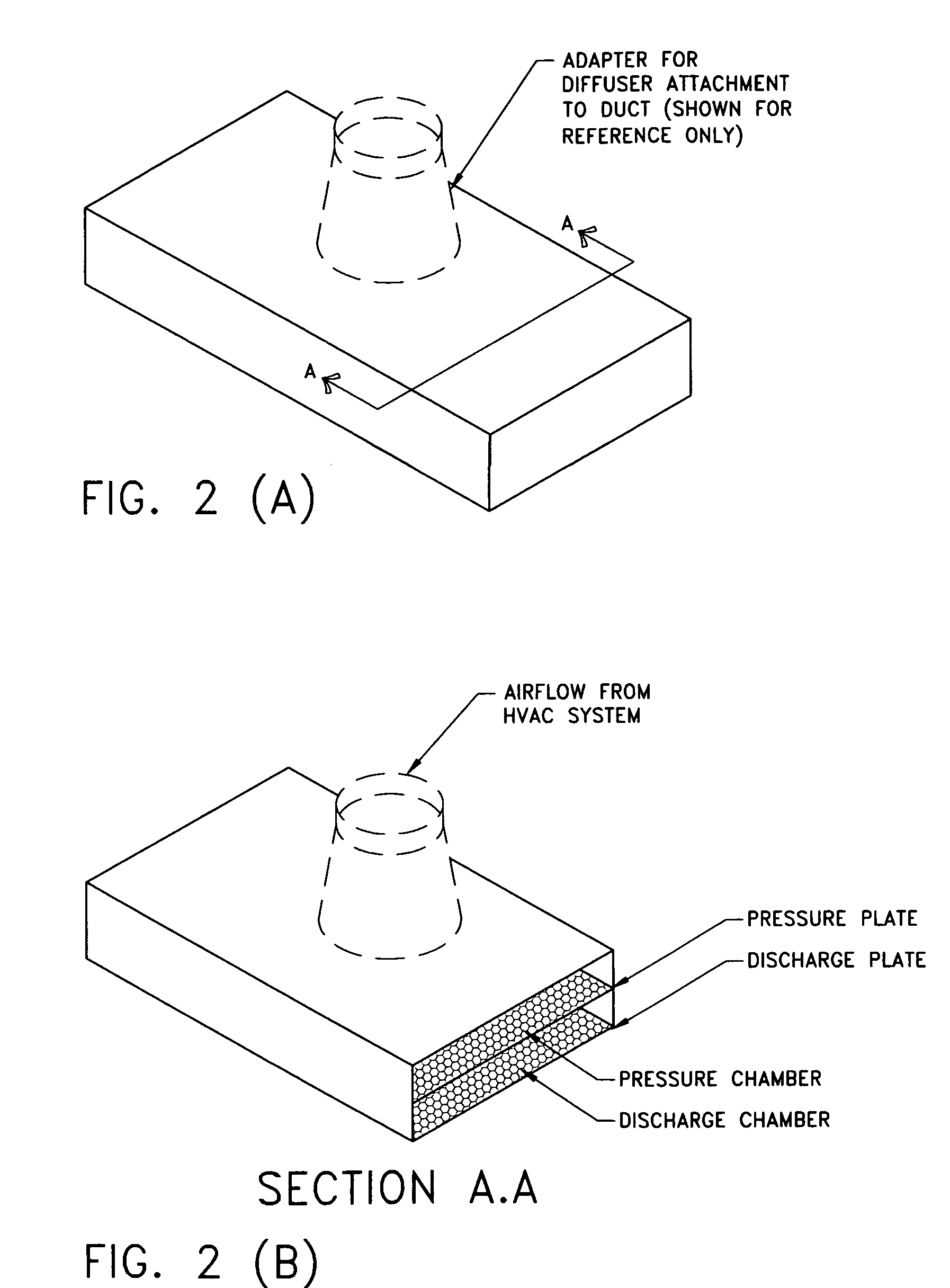
[0020]The diffuser assembly for non-turbulent air flow replaces currently used diffusers in applications where turbulence and uncontrolled dispersion of the air from a ventilation or A / C unit do not meet the requirements of the system. Representative examples include: the use of ventilation or A / C as make-up air for grease exhaust hoods for cooking over open flame or heated grill surfaces; ventilation or A / C make-up air for exhaust hoods in laboratories where the hoods are used to exhaust toxic or noxious fumes; for the ventilation or A / C provided make-up air for spray booths where the over-spray is filtered and exhausted outside the facility; and in meeting rooms, restaurants and auditoriums where less turbulence reduces unwanted drafts and air currents. With the make-up air being provided with current diffusers that employ louvers or deflector plates to direct air flow there is still turbulence that causes unwanted fumes from the heated grill or open flame cooking surfaces, or lab...


PUM


Abstract

The invention is an air flow diffuser that produces an even and non-turbulent flow of air from ventilation or A / C. The diffuser combines a pressure chamber and a discharge chamber to produce a non-turbulent even flow of air perpendicular to the face of the discharge chamber. The pressure and discharge chambers are contiguous with the ducted air flowing first into the pressure chamber and then into the discharge chamber from which chamber the non-turbulent, evenly flowing air flows into the space. Though the diffuser is developed for a downward air flow, the diffuser can be constructed in several shapes, such as triangular, allowing air flow in any direction that is perpendicular to the plane of the discharge plate.

Description

CROSS-REFERENCE TO RELATED APPLICATIONS[0001]Not ApplicableSTATEMENT REGARDING FEDERALLY SPONSORED RESEARCH AND DEVELOPMENT[0002]Not ApplicableREFERENCE TO SEQUENCE LISTINGS[0003]Not ApplicableBACKGROUND OF THE INVENTION[0004]This invention is in the field of endeavor dealing with ventilation with specific air distribution.[0005]Current air supply diffusers are designed with deflectors or louvers for directional flow so as to direct air flow to specific areas of a space without regard to turbulence and contained air flow. This directed air flow is acceptable for basic heating, cooling, ventilating and / or other similar applications within an enclosed space. However, drafts and other turbulent conditions may be created which may prove to be “unacceptable” for applications in certain environments. Therefore a more controlled and non-turbulent air flow is required for providing a more comfortable or even distribution of air.BRIEF SUMMARY OF THE INVENTION[0006]The invention resolves the ...

Claims


Application Information

Patent Timeline
Patent Type & Authority Applications(United States)
IPC IPC(8): F24F13/068
CPCF24F13/068F24F7/10
Inventor HIRSCH, H. HENRY
Owner HIRSCH H HENRY
Why Eureka
Try Eureka