Device for conveying air to a person

a technology for conveying devices and air, applied in the field of conveying devices, can solve the problems of unsuitable convex bodies for conveying heated air, and achieve the effect of improving the quick and even distribution of supplied air and low permeability values

Active Publication Date: 2010-06-24
THE SURGICAL INT
View PDF34 Cites 8 Cited by
  • Summary
  • Abstract
  • Description
  • Claims
  • Application Information

AI Technical Summary

Benefits of technology

[0033]For a quick distribution of air supplied to the inlet end of the main duct, it is advantageous according to the invention if the plurality of welds, at the inlet end, in line with each first and, if present, second series comprises a third connecting weld, which is in particular pointed. It is in this case furthermore advantageous if the connection outside the main duct is provided upstream of the inlet thereof and is designed in such a manner that the supply direction of the air is transverse to the outer sheet.
[0034]According to another embodiment, in which the air chamber has an elongate shape; and in which the connection is provided on a longitudinal side of the elongate form, it is advantageous according to the invention if the main duct is a curved duct which extends from the connection to the centre of said air chamber, viewed in the width direction of the elongate air chamber; if the first series delimits the inner-bend side of the main duct; if a third ancillary duct extends on the outer-bend side of the main duct which is substantially straight and extends in the longitudinal direction of the elongate air chamber; if the plurality of welds comprises a third series of elongate third welded strips which are in line with third intermediate spaces, which third series delimits that side of the third ancillary duct which is adjacent to the main duct; and if the plurality of welds comprises one or more outer-bend welded strips which are directed obliquely towards the third series in order, together with one or more third welded strips of the third series which are situated downstream of the outer-bend welded strips, to form the outer bend of the main duct. This other embodiment is inter alia required when air is to be conveyed to the upper body of a person with one or both arms extended in the transverse direction of the body of the person. In practice, it has been found that it is desirable in this case for the connection to be situated on a longitudinal side. By designing the main duct in the form of a curve extending from the connection to the transverse centre of the air chamber, with the inner-bend side turned away from the longitudinal centre of the air chamber and designed as first series, and providing a third ancillary duct in the longitudinal direction of the air chamber, the boundary of which meets the outer-bend boundary of the main duct, a quick and even distribution of supplied air across the air chamber can be achieved despite said substantially unfavourable positioning of the connection.
[0035]In order to further improve the quick and even distribution of supplied air across the air chamber, it is advantageous in the case of this other embodiment if a fourth ancillary duct extends on that side of the third ancillary duct which is turned away from the main duct, and extends parallel to the third ancillary duct; if the plurality of welds comprises a fourth series of elongate fourth welded strips which are in line with fourth intermediate spaces, which fourth series forms the boundary between the third and fourth ancillary ducts; and if the length of each of these fourth intermediate spaces, viewed in the non-inflated state, is in each case greater than the length of the first intermediate spaces.
[0036]In the case of this further embodiment, it is advantageous, for a quick and even distribution of supplied air along the transverse side of the air chamber which is situated opposite the inlet of the main duct, if the one or more ancillary ducts have a first end and if, viewed in the transverse direction of the elongate chamber, these first ends are situated substantially next to the inlet end of the main duct; and if, viewed in the longitudinal direction of the elongate air chamber, the plurality of welds upstream of the inlet end comprises one or more fourth connecting welds.
[0037]If this other embodiment is intended for conveying air to the upper body of a person with both arms in the transverse direction of the body of the person, it is advantageous according to the invention if the elongate air chamber, viewed in the longitudinal direction thereof, has a longitudinal centre and is mirror-symmetrical with respect to a mirror axis which is at right angles to the longitudinal axis of the elongate air chamber and crosses this longitudinal centre. Thus, a universal device is produced which, in use and depending on preference, offers the choice of supplying the air via the connection on the left-hand or right-hand side of the person. For an efficient distribution of the air supplied, it is in this case particularly advantageous if the connections are provided at approximately one quarter and three quarters of the length of the elongate chamber.
[0038]According to the invention, it is furthermore advantageous if the inner sheet has an evenly distributed permeability to air of <300 mm / sec, in particular ≦200 mm / sec, measured according to ISO 9237:1995(E). This standard defines the permeability to air as: “Velocity of an air flow which passes through a test specimen at right angles under specified conditions of the test environment, pressure drop and time”. The specified conditions, measuring procedure, etc. can be found in said ISO 9237:1995(E). The permeability to air of <300 mm / sec, in particular ≦200 mm / sec, results in a low velocity of air coming from the inner sheet, which counteracts any draught effects when this air flows along the body of the person. These low permeability values are possible in particular with the method of producing the plurality of welds according to the invention without this being to the detriment of an even temperature (that is to say that the temperature is approximately equal at each location of the inner sheet) of the air flowing out of the inner sheet.

Problems solved by technology

Such a convex body is not suitable for conveying heated air to the person in an evenly distributed manner.

Method used


Image

  • Device for conveying air to a person
  • Device for conveying air to a person
  • Device for conveying air to a person

Examples


third embodiment

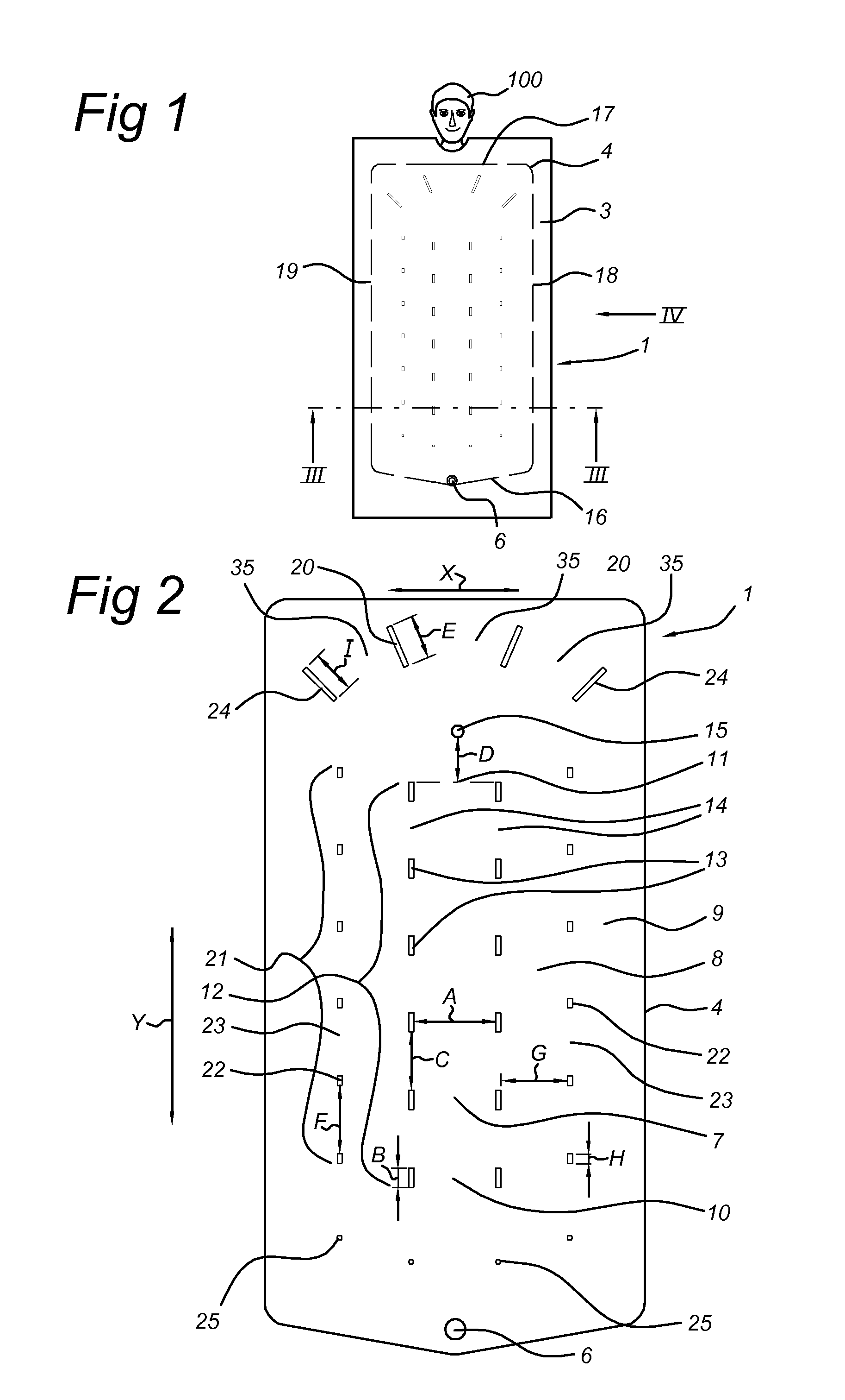
[0099]FIG. 7 shows the third embodiment, model ‘paediatric’, which is generally denoted by reference numeral 101. It is composed of an inner sheet which is permeable to air and an outer sheet which is impermeable to air is, both sheets being connected to one another by a peripheral weld 104 in order to define an air chamber between them, and a connection 106 is provided in the outer sheet for blowing in air. It has two main ducts 107, which are separated from one another by two welded strips 136 and a spot weld 137. The connection 106 is in line with the welded strips 136 at some distance in front of the inlets 110 of both main ducts 107. The main ducts 107 each have, in the non-inflated state, a width A. The longitudinal sides of the main ducts 107 which are turned away from one another are each delimited by a first series of first welded strips 113, which each have a length B, with first intermediate spaces 114 having a length C between them. At a distance D downstream from the ou...

fourth embodiment

[0100]FIG. 8 shows the fourth embodiment, model ‘half upper’, which is denoted overall by reference numeral 151. It is composed of an inner sheet which is permeable to air and an outer sheet which is impermeable to air, both sheets being connected to one another by a peripheral weld 154 in order to define an air chamber between them, and two connections 156 are provided in the outer sheet for blowing in air. It has two main ducts 157, which run at an angle with respect to one another. Depending on the available space around the patient, the one or the other connection 156 will be used for blowing in air and the connection which is not used will be closed, as has been described for the embodiment from FIGS. 5-6. In that case, the main duct 157 which is in use and connected to the connection 156, will then serve as main duct.

[0101]In the embodiment according to FIG. 8, each main duct is delimited by two first welded strips 163, which are provided a distance C apart so as to leave an i...


PUM


Abstract

The invention relates to a device for conveying heated air to a person and comprises an air-permeable inner sheet and an air-impermeable outer sheet which are connected to one another by welds in order to form a panel-like shape in the inflated state. The welds produce a main duct having, viewed at the inlet end and in the non-inflated state, a main duct width. The main duct is delimited by at least one first series of elongate first welded strips, the first intermediate spaces which are in line with one another. The length of each of these first intermediate spaces, viewed in the non-inflated state, is in each case smaller than the main duct width. The length of each first welded strip is at least 15% of the main duct width and at most 80% of the main duct width.

Description

BACKGROUND OF THE INVENTION[0001]The present invention relates to a device for conveying air, in particular heated air, to a person, in which the device comprises an air-permeable inner sheet to be turned towards the person and an air-impermeable outer sheet to be turned away from the person; in which the inner sheet and the outer sheet are connected to one another in an air-tight manner by a peripheral weld which, together with the inner and outer sheet, defines an air chamber; in which the device is provided with at least one connection for blowing in air; in which the inner sheet and the outer sheet, in the air chamber, are connected to one another by a plurality of welds in such a manner that, when air is blown into the device via the connection, the former assumes a panel-like shape having a plurality of air ducts which are connected to one another; in which the plurality of ducts comprises a main duct and one or more ancillary ducts; in which the main duct has an inlet end and...

Claims


Application Information

Patent Timeline
Patent Type & Authority Applications(United States)
IPC IPC(8): A61F7/08
CPCA61F2007/006A61F7/0097
Inventor VAN LIEBERGEN, ANTONIUS JOSEPHUSCAMPE, ROYOFFICIER, ARTHUR EVERARDUS
Owner THE SURGICAL INT
Why Eureka
Try Eureka