Radially segmented apodized diffractive multifocal design for ocular implant

a diffractive multifocal and ocular implant technology, applied in the field of ocular implants, can solve the problems of less transparent lenses and vision deterioration, and achieve the effects of reducing glare, prolonging depth of focus, and reducing step height smoothly

Active Publication Date: 2010-06-24
ALCON INC
View PDF70 Cites 87 Cited by
  • Summary
  • Abstract
  • Description
  • Claims
  • Application Information

AI Technical Summary

Benefits of technology

[0008]Other embodiments of the present invention provide a method to correct for visual impairment of aphakia. In one embodiment this involves removing a natural lens from an eye when the lens may be diseased or damaged through accident. Next a radially segmented apodized diffractive multifocal IOL may be inserted within the eye and secured and positioned with a number of haptics. The diffractive regions or zones of the radially segmented apodized diffractive multifocal IOL may simultaneously pass optical energy to both near and distant focal points. Each radially segmented apodization zone can have a unique focal length. The focal length differences can be adjusted to provide three (or more) distinct focal lengths (base power, plus two add powers) or to provide an add power with significantly extended depth of focus. Echelettes within each radially segmented apodization zone may have a smoothly reduced step height to shift the energy balance from the near image to the distant image and thus reduce the glare perceived when viewing a discrete, distant light source. Thus, the radially segmented apodized diffractive portion of the multifocal IOL may pass optical energy in bright optical conditions while the outer refractive region may pass optical energy to distance vision in dim optical conditions.
[0009]Yet another embodiment of the present invention provides a method to correct visual impairment. This method involves passing optical energy to the retina wherein the optical energy may be imaged. This optical energy is passed with a radially segmented apodized diffractive multifocal IOL typically located within the eye and used to replace the natural lens. The radially segmented apodized diffractive multifocal IOL may pass optical energy in both photopic and mesopic conditions using a number of radially segmented apodization zones having unique focal lengths. The focal length differences can be adjusted to provide three (or more) distinct focal lengths (base power, plus two add powers) or to provide an add power with significantly extended depth of focus.

Problems solved by technology

Age and / or disease often cause the lens to become less transparent.
Thus, vision deteriorates because of the diminished light which can be transmitted to the retina.

Method used


Image

  • Radially segmented apodized diffractive multifocal design for ocular implant
  • Radially segmented apodized diffractive multifocal design for ocular implant
  • Radially segmented apodized diffractive multifocal design for ocular implant

Examples


Embodiment Construction

[0018]Preferred embodiments of the present invention are illustrated in the FIGs., like numerals being used to refer to like and corresponding parts of the various drawings.

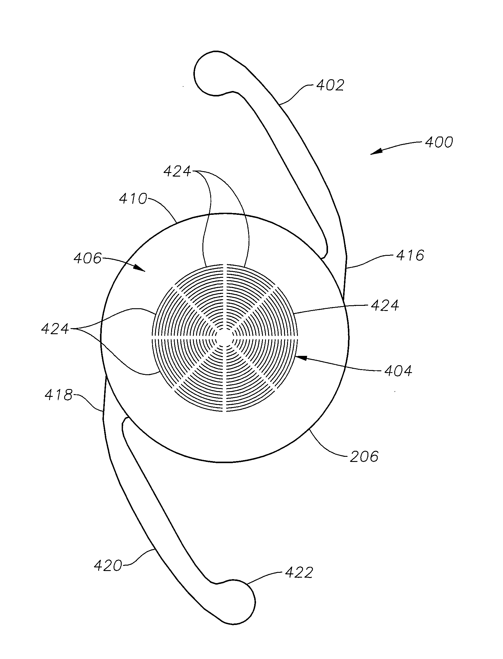
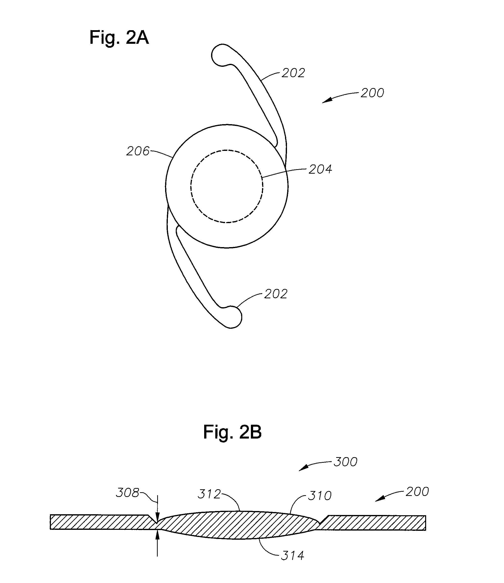
[0019]A radially segmented apodized diffractive multifocal design for ocular implant is provided by embodiments of the present invention. Embodiments of the ocular implant can comprise a radially segmented apodized diffractive multifocal intraocular lens (IOL) optic and a number of haptics. The radially segmented apodized diffractive multifocal IOL optic may pass optical energy in both photopic and mesopic conditions. The radially segmented apodized diffractive multifocal IOL can comprise a number of radially segmented apodization zones, each radially segmented apodization zone having a unique focal length. The haptics mechanically couple to the apodized diffractive multifocal IOL optic in order to position and secure the apodized diffractive multifocal IOL within the eye. The radially segmented apodized diffract...


PUM


Abstract

A radially segmented apodized diffractive multifocal IOL for ocular implant is provided. The ocular implant can comprise a radially segmented apodized diffractive multifocal intraocular lens optic and a number of haptics. The radially segmented apodized diffractive multifocal IOL may pass optical energy in both photopic and mesopic conditions. The radially segmented apodized diffractive multifocal IOL includes a number of radially segmented apodization zones, each radially segmented apodization zones having a unique focal length. The haptics mechanically couple to the apodized diffractive multifocal IOL optic in order to position and secure the apodized diffractive multifocal IOL within the eye. The radially segmented apodized diffractive multifocal IOL may include both a diffractive region and a refractive region.

Description

[0001]This application claims priority to U.S. Provisional Application Ser. No. 61 / 139,119 filed on Dec. 19, 2008.TECHNICAL FIELD OF THE INVENTION[0002]The present invention relates generally to ocular implants, and more particularly, to diffractive multifocal intraocular lenses (IOLs).BACKGROUND OF THE INVENTION[0003]The human eye in its simplest terms functions to provide vision by transmitting light through a clear outer portion called the cornea, and focusing the image by way of a lens onto a retina. The quality of the focused image depends on many factors including the size and shape of the eye, and the transparency of the cornea and lens. Age and / or disease often cause the lens to become less transparent. Thus, vision deteriorates because of the diminished light which can be transmitted to the retina. This deficiency in the lens of the eye is medically known as a cataract. An accepted treatment for this condition is surgical removal of the lens and replacement of the lens func...

Claims


Application Information

Patent Timeline
Patent Type & Authority Applications(United States)
IPC IPC(8): A61F2/16
CPCA61F2/1654A61F2/1618A61F2002/1699
Inventor SCHAPER, JR., DALE T.
Owner ALCON INC
Why Eureka
Try Eureka