Latching solenoid energy reserve

a solenoid and energy reserve technology, applied in non-electric variable control, process and machine control, instruments, etc., can solve the problem of significant turf damag

Active Publication Date: 2010-06-24
RAIN BIRD CORP
View PDF101 Cites 82 Cited by
  • Summary
  • Abstract
  • Description
  • Claims
  • Application Information

AI Technical Summary

Benefits of technology

[0009]In a further embodiment, the invention may be characterized as an irrigation device including an actuator configured to control water flow to at least one water delivery device, a first stored energy source configured to power the actuator to effect irrigation via the at least one water delivery device, and a second stored energy source which is separate from the first stored energy source, wherein the second stored energy source is configured to power the actuator to terminate the irrigation via the at least one water delivery device. The irrigation devices further include a controller configured to cause the first stored energy source to power the actuator to effect the irrigation, responsive to an instruction to provide irrigation, and to cause the second stored energy source to power the actuator to terminate the irrigation responsive to a termination condition.

Problems solved by technology

If power is lost and the latching solenoid cannot be closed, significant turf damage can occur due to the large amount of unintended irrigation that would continuously flow until the fault is discovered and manually corrected.

Method used


Image

  • Latching solenoid energy reserve
  • Latching solenoid energy reserve
  • Latching solenoid energy reserve

Examples


Embodiment Construction

[0017]The following description is not to be taken in a limiting sense, but is made merely for the purpose of describing the general principles of exemplary embodiments. The scope of the invention should be determined with reference to the claims.

[0018]Reference throughout this specification to “one embodiment,”“an embodiment,” or similar language means that a particular feature, structure, or characteristic described in connection with the embodiment is included in at least one embodiment of the present invention. Thus, appearances of the phrases “in one embodiment,”“in an embodiment,” and similar language throughout this specification may, but do not necessarily, all refer to the same embodiment.

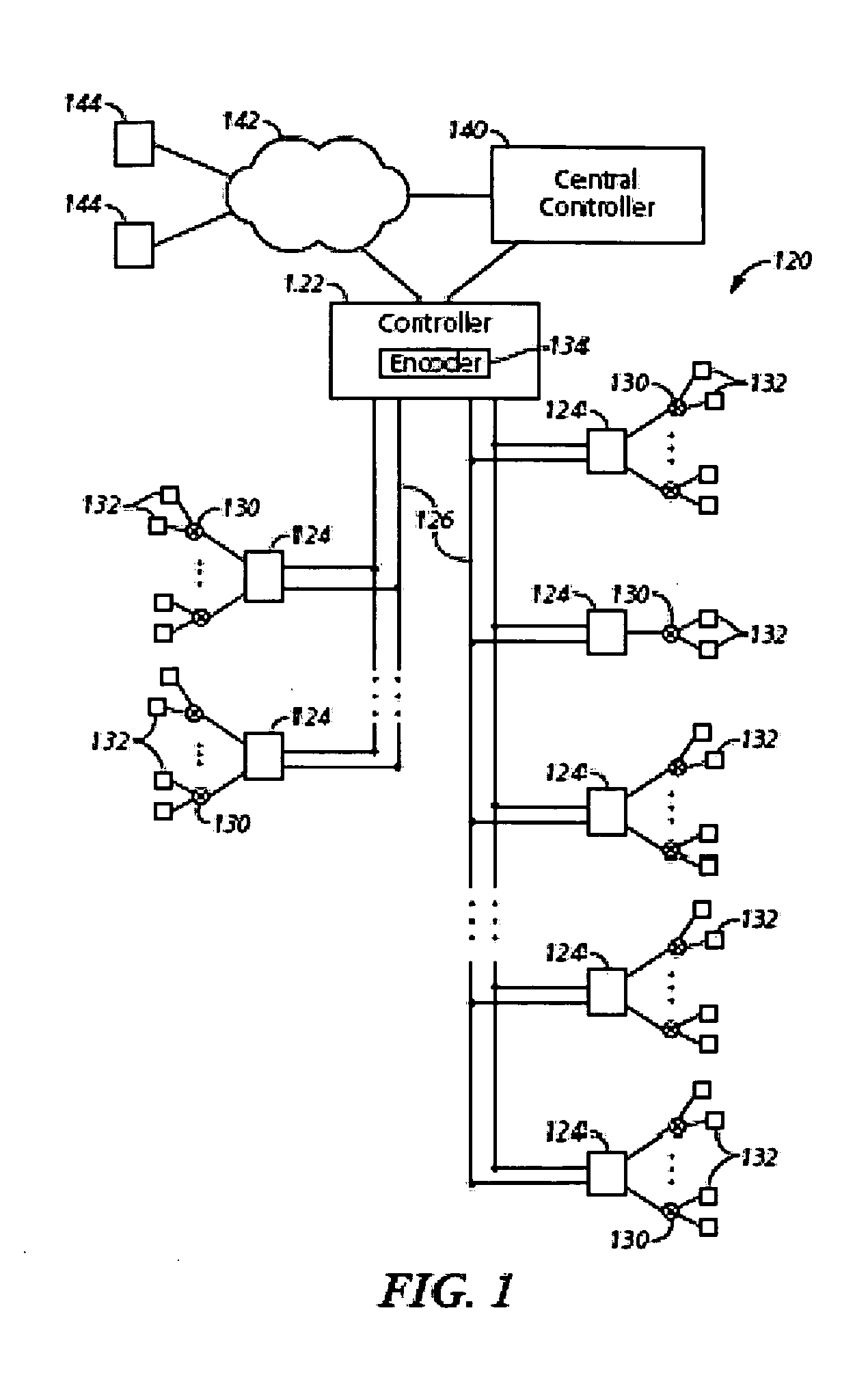
[0019]FIG. 1 depicts a simplified block diagram of an irrigation system 120 according to some embodiments. The irrigation system includes an irrigation controller 122 and one or more remote irrigation devices 124 coupled with the irrigation controller through one or more two-wire power lin...


PUM


Abstract

An irrigation device including an actuator configured to control water flow to at least one water delivery device, a first stored energy source configured to power the actuator to effect irrigation via the at least one water delivery device, and a second stored energy source which is separate from the first stored energy source, wherein the second stored energy source is configured to power the actuator to terminate the irrigation via the at least one water delivery device. The irrigation devices further includes a controller configured to cause the first stored energy source to power the actuator to effect the irrigation, responsive to an instruction to provide irrigation, and to cause the second stored energy source to power the actuator to terminate the irrigation responsive to a termination condition.

Description

BACKGROUND OF THE INVENTION[0001]1. Field of the Invention[0002]The present invention relates generally to irrigation control devices, and more particularly to the powering of irrigation control devices using an energy reserve.[0003]2. Discussion of the Related Art[0004]Typical irrigation control systems cooperate with water valves and pumps to control the flow of irrigation water through a variety of water dispensing devices, including sprinklers, rotors, drip-lines, and other water delivery devices. These control systems are used in a wide variety of irrigation applications, from residential and commercial landscapes to golf course and agricultural irrigation. Rotors, for example, irrigate by throwing a jet or spray of water that is rotated about a generally vertical axis. Rotors are supplied with water from water supply lines that are usually installed below ground and are typically actuated by electric solenoid-controlled valves.[0005]Water flow through a rotor or other water de...

Claims


Application Information

Patent Timeline
Patent Type & Authority Applications(United States)
IPC IPC(8): A01G25/16G05D7/06F16K31/02
CPCA01G25/16Y10T137/86397
Inventor CRIST, TIMOTHY J.
Owner RAIN BIRD CORP
Why Eureka
Try Eureka