System and method for rotor blade health monitoring

a technology of health monitoring and rotor blades, applied in the direction of mechanical roughness/irregularity measurement, testing/monitoring control system, instruments, etc., can solve the problems of fatigue, stress, affecting the health of the rotor blade, and ultimately cracking the rotor blad

Active Publication Date: 2010-06-24
GENERAL ELECTRIC CO
View PDF41 Cites 67 Cited by
  • Summary
  • Abstract
  • Description
  • Claims
  • Application Information

AI Technical Summary

Problems solved by technology

Various factors adversely affect health of the rotor blades and le

Method used


Image

  • System and method for rotor blade health monitoring
  • System and method for rotor blade health monitoring
  • System and method for rotor blade health monitoring

Examples


Embodiment Construction

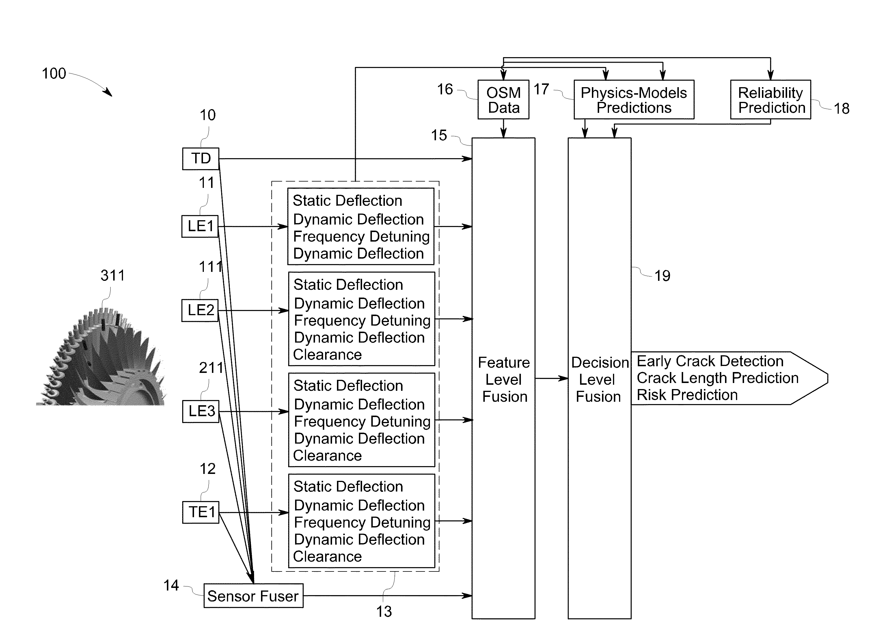
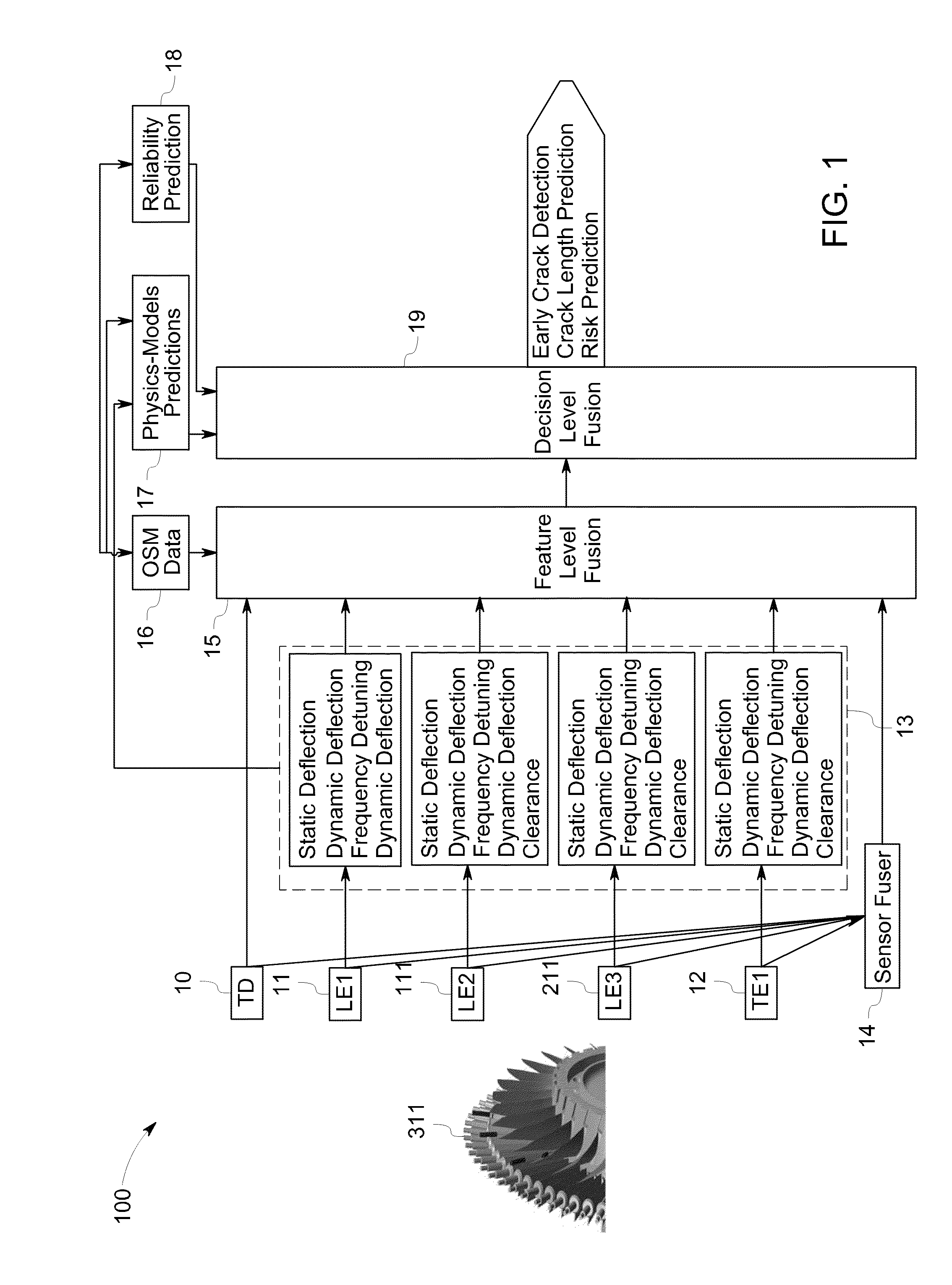
[0016]FIG. 1 is a block diagram of a system 100 in accordance with one embodiment of the invention for monitoring health of rotor blades 311. The system 100 includes at least one sensor 11, 12 for sensing arrival of the rotor blade 311 with respect to a reference key phasor. In the illustrated embodiment, two types of sensors are shown including leading edge sensor (LE) 11 and trailing edge sensor (TE) 12. In the block diagram, the system includes three leading edge sensors (LE1, LE2 and LE3) 11, 111, 211 and one trailing edge sensor (TE) 12. However, the number of each type of sensor depends on a variety of factors including, for example, the number of stages of rotor blades 311 and the number of rotor blades 311 in the stages.

[0017]In one aspect of the invention, all sensors can interchangeably be used as leading edge and trailing edge sensors. The leading edge sensors sense the arrival of a leading edge of the rotor blades 311 whereas the trailing edge sensors sense the arrival o...


PUM


Abstract

A system for rotor blade health monitoring include time of arrival (TOA) sensors and a controller comprising a processor configured for obtaining TOA signals indicative of times of arrival of rotating rotor blades from the respective TOA sensors and for determining initial features from the TOA signals; and a feature level fuser configured for fusing the initial features received from the processor for use in evaluating health of the rotating rotor blades.

Description

BACKGROUND[0001]The invention relates generally to systems and methods for monitoring health of rotor blades.[0002]Rotor blades or rotating blades are used in many devices with several examples including compressors, turbines, and engines. An axial compressor, for example, has a series of stages with each stage comprising a row of rotor blades followed by a row of stator blades.[0003]Axial compressors are used in a number of devices with one example being land based gas turbines. Land based gas turbines typically include an inlet section to accelerate the air, a compressor to compress the incoming air, a combustor for burning compressed air and fuel, and a turbine to covert thermal energy into mechanical energy to drive a generator to produce required power. To develop adequate pressure for combustion, the compressor has about eighteen stages with each stage having stator and rotor blades. Each blade of the compressor has distinct natural frequencies.[0004]Various factors adversely ...

Claims


Application Information

Patent Timeline
IPC IPC(8): G06F19/00
CPCF01D21/003G05B23/0221F05D2230/80G05B23/0245G05B23/0235F01D21/00F01D25/00G01D5/12G01H11/06G01M15/14
Inventor RAI, SUDHANSHUJAMMU, VINAY BHASKARBADAMI, VIVEK VENUGOPALPANDEY, ACHALESH KUMARPRABHU, RAHUL SRINIVASBEHERA, AJAY KUMARBHATTACHARYA, ANINDARAJAGOPALAN, VENKATESHNAITHANI, NIDHI
Owner GENERAL ELECTRIC CO
Why Eureka
Try Eureka