Piston device for internal combustion engines

a technology for internal combustion engines and pistons, which is applied in the direction of machines/engines, braking systems, transportation and packaging, etc., can solve the problems of unsatisfactory driving conditions, high-speed and high-load driving, oil consumption during high-boost driving, etc., to prevent the rise in oil pressure at the piston land above the second compression ring, and reduce the upward rise of oil.

Active Publication Date: 2010-07-01
TEIKOKU PISTON RING CO LTD
View PDF7 Cites 14 Cited by
  • Summary
  • Abstract
  • Description
  • Claims
  • Application Information

AI Technical Summary

Benefits of technology

[0013]In the invention according to claim 1, 2, or 3, the second compression ring contains a notch extending from the inner circumference to the outer circumference on the lower surface of at least one of the ends of the ring; and the gap at the notch on the second compression ring is larger than the gap on the first compression ring, and the gap at the section other than the notch on the second compression ring is the same or smaller than the gap on the first compression ring. When the second compression ring makes contact with the lower surface of the ring groove of the piston during driving at high-speeds and high-loads, the blow-by gas flowing into the ring groove escapes from the inner circumferential side of the ring by way of the notch on the lower surface of the ring end to the outer side, so that a rise in pressure at the piston land above the second compression ring can be prevented and therefore the oil can be prevented from rising upwards. Moreover, when the second compression ring makes contact with the upper surface of the ring groove of the piston during driving under high boost conditions, the upward rise of oil can be reduced because the gap is small. The second compression ring moreover has a tapered surface on the upper section of the ring outer circumference which serves to suppress the oil scraping effect when the ring is rising so that oil consumption can be reduced further.
[0014]The invention according to claim 4 is capable of improving the oil scraping effect by way of the undercut.
[0015]The invention according to claim 5 suppresses an upward rise of oil, compared to when an arc shape is utilized.
[0016]The invention according to claim 6 can prevent an upward rise of oil, and reduce oil consumption further because the blow-by gas can easily enter into the gap during driving at high-speeds and high loads.

Problems solved by technology

However, on the rings disclosed in the Japanese unexamined utility model application publication No. 5-030624 and Japanese unexamined patent application publication No. 48-21014, the outer circumferential surfaces are both formed as an axial parallel surface so that oil consumption during driving at high-speeds and high-loads and driving under high-boost conditions is still not always satisfactory.

Method used


Image

  • Piston device for internal combustion engines
  • Piston device for internal combustion engines
  • Piston device for internal combustion engines

Examples


Embodiment Construction

[0042]An embodiment of the present invention is described next while referring to the drawings.

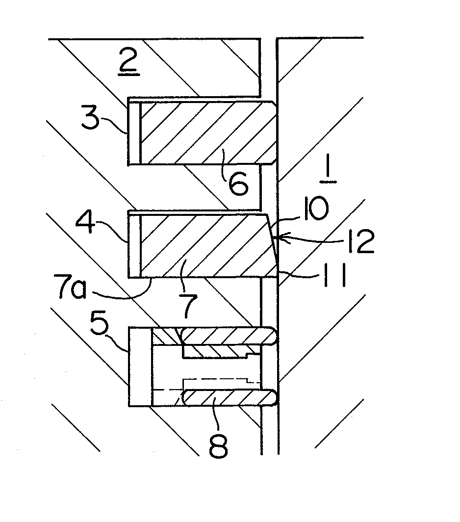
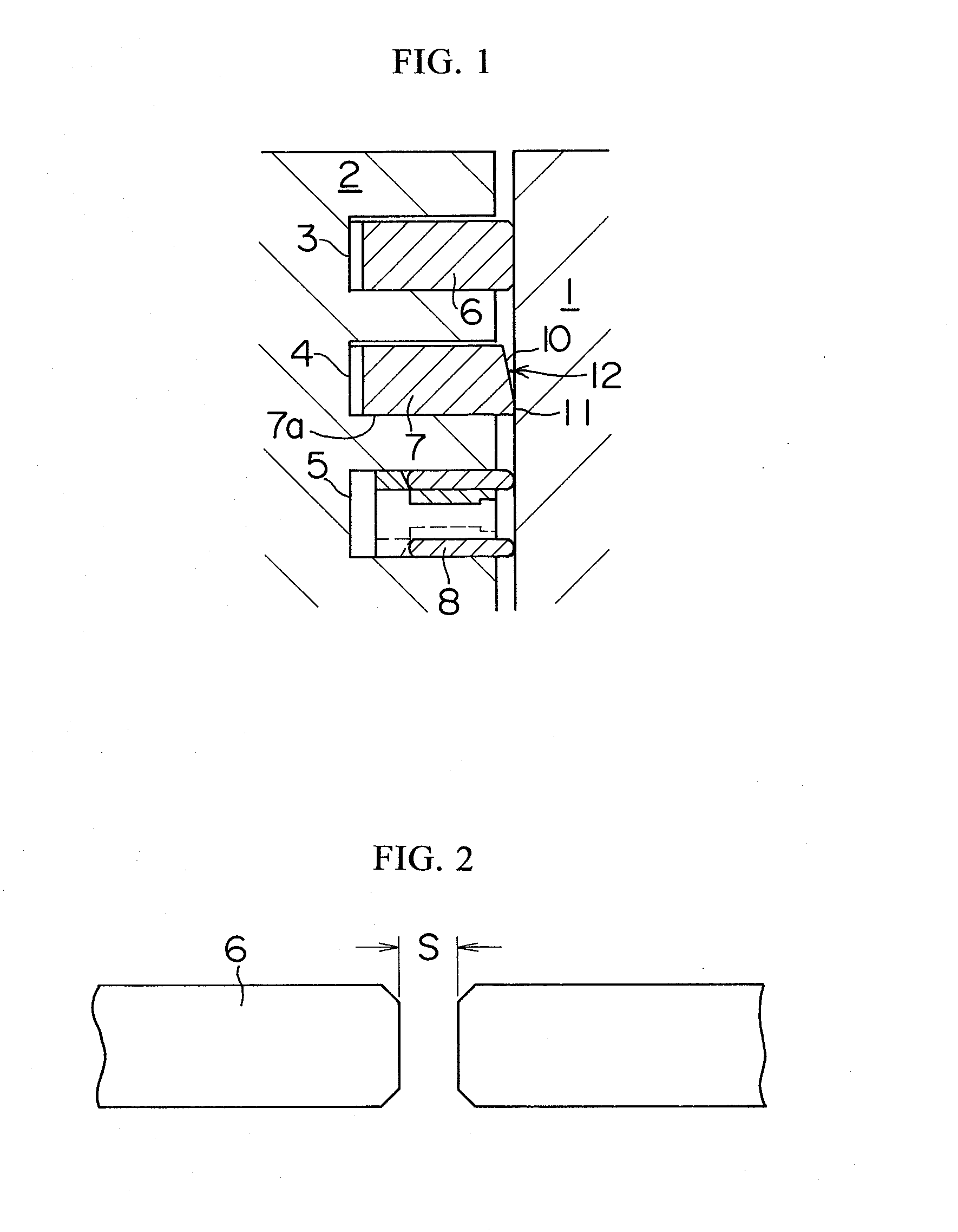
[0043]In FIG. 1, multiple ring grooves 3, 4, and 5 are formed on the outer circumferential surface of a piston 2 that moves back and forth inside a cylinder 1 of an internal combustion engine. A first compression ring 6, a second compression ring 7, and a combined oil ring 8 are respectively installed in the ring grooves 3, 4, and 5 in order from the combustion chamber side. The first compression ring 6 and the second compression ring 7 possess a compression function, and mainly serve to suppress blow-by gas from the combustion chamber and also render the effect of scraping oil on the cylinder wall.

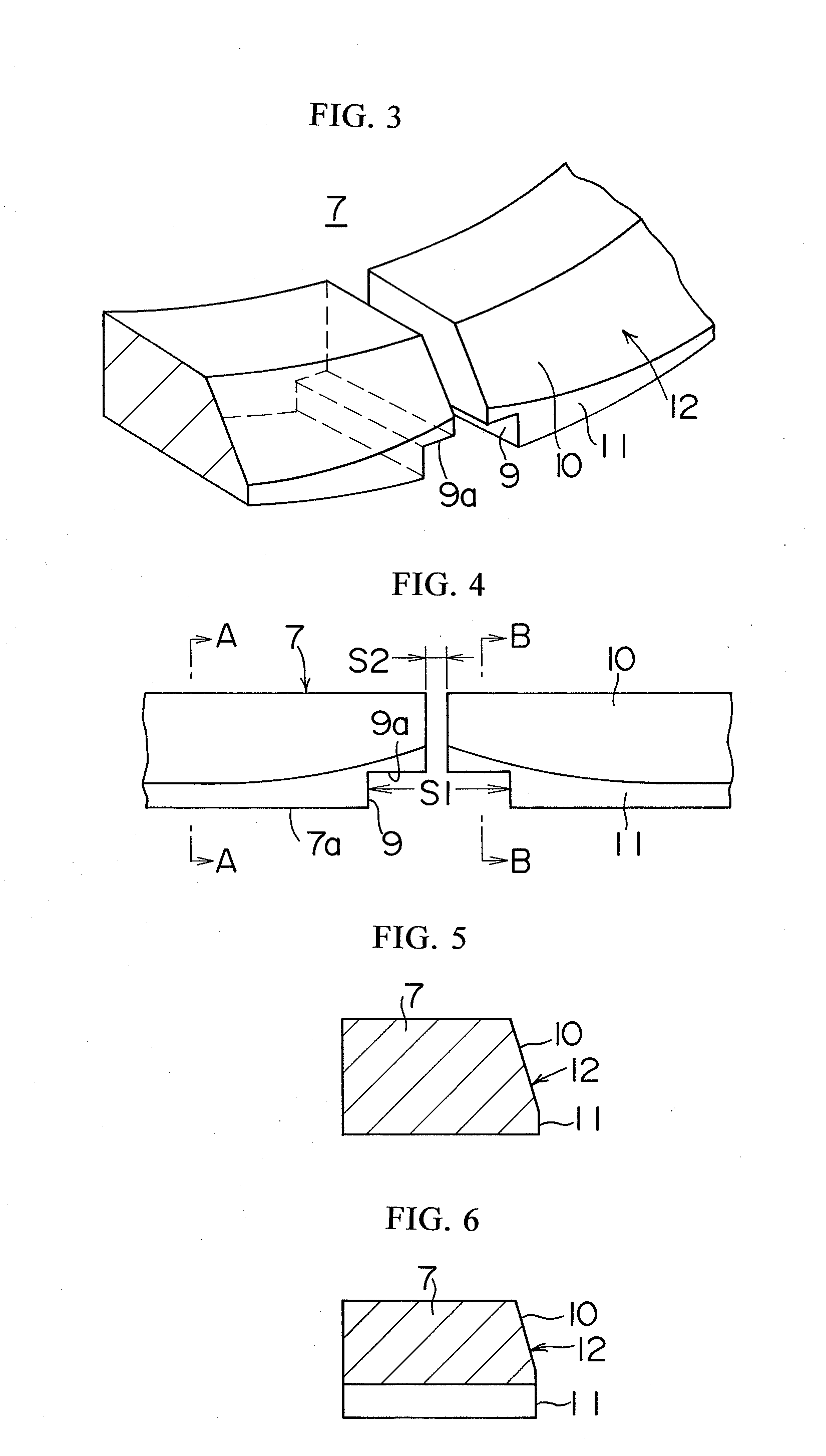
[0044]As shown in FIG. 3 through FIG. 6, the second compression ring 7 contains notches 9 having a rectangular cross section and extending from the inner circumference to the outer circumference on the lower surface of the pair of ends of the ring. The gap S1 between the ring ends at the notches...


PUM


Abstract

A piston device for internal combustion engines includes a first compression ring and a second compression ring in an outer circumference of a piston, wherein the second compression ring includes a notch extending from the inner circumference to the outer circumference on a lower surface of at least one of a pair of ends of the ring, and a gap between the ring ends at the notch on the second compression ring is larger than a gap between the ring ends of the first compression ring, and a gap between the ring ends at the section other than the notch on the second compression ring is the same or smaller than the gap between the ring ends of the first compression ring, and the second compression ring contains an outer circumferential surface comprised of a tapered surface decreasing the ring radial thickness towards the upper side, and an axial parallel surface formed below the tapered surface. Instead of the axial parallel surface, the second compression ring may utilize a tapered surface with a taper angle smaller than the taper angle of the above tapered surface; or may utilize a tapered surface decreasing the ring radial thickness towards the lower side.

Description

BACKGROUND OF THE INVENTION[0001]1. Field of the Invention[0002]The present invention relates to a piston device for internal combustion engines containing compression rings capable of reducing oil consumption during driving at high-speeds and high loads and driving under high-boost conditions.[0003]2. Description of the Related Art[0004]To reduce oil consumption during driving at high-speeds and high-loads and driving under high-boost conditions, the Japanese unexamined utility model application publication No. 5-030624 proposes a compression ring for internal combustion engines. The gap between the both ends of the second compression ring is reduced to the utmost to an extent where the ring ends barely avoid coming in contact, and a notch extending from the outer circumference to the inner circumference is formed on the lower surface of at least one of the ends of the second compression ring, and the gap between the ring ends at the notch on the second compression ring is formed l...

Claims


Application Information

Patent Timeline
Patent Type & Authority Applications(United States)
IPC IPC(8): F16J9/12F02F3/00
CPCF02F5/00F16J9/14F16J9/20
Inventor ISHIDA, MASAO
Owner TEIKOKU PISTON RING CO LTD
Why Eureka
Try Eureka