Electrical power tool

a technology of electric power tools and tip tools, which is applied in the direction of portable power-driven tools, manufacturing tools, drilling machines, etc., can solve the problems of difficult to recognize a slight difference in the degree to which the trigger is pulled, and is possible to perform only rough speed control, so as to finely control the speed of the tip tool

Active Publication Date: 2010-07-01
ORMON CORP +1
View PDF15 Cites 17 Cited by
  • Summary
  • Abstract
  • Description
  • Claims
  • Application Information

AI Technical Summary

Benefits of technology

[0026]According to the present invention, since the operation switch, which is rotated around the axis parallel to the rotation axis of the tip tool, and determines the rotation direction and the rotation speed of the tip tool according to the rotation direction and the rotation angle of the operation switch, is provided, the user can intuitively grasp the operation amount of the operation switch, and finely control the speed of the tip tool. In addition, the grip is rotatable with respect to the tool body, whereby the electrical power tool can be used in various work spaces by changing the shape of the electrical power tool.

Problems solved by technology

However, it is difficult to recognize a slight difference in the degree to which the trigger is pulled in.
Thus, there was a problem that it was possible to perform only rough speed control.

Method used


Image

  • Electrical power tool
  • Electrical power tool
  • Electrical power tool

Examples


Embodiment Construction

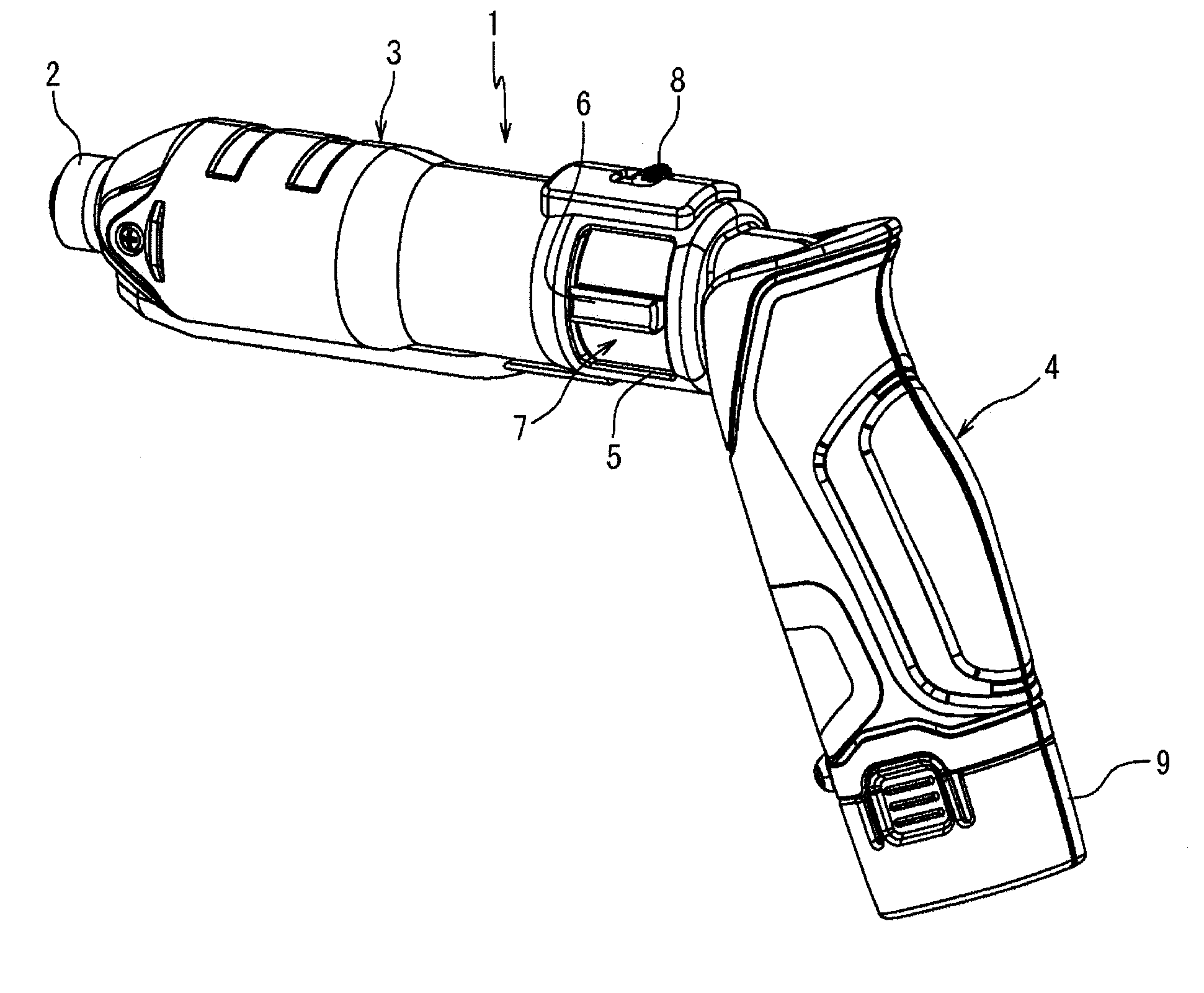
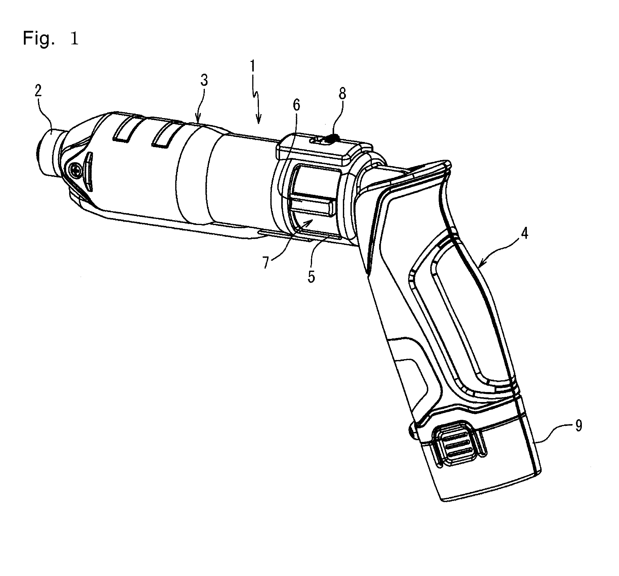
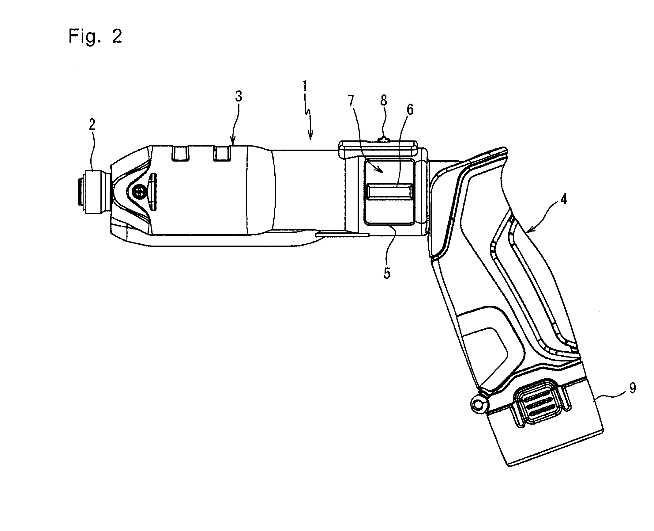
[0039]The present invention will hereinafter be described with reference to the drawings. FIGS. 1 to 3 show an electrical power tool 1 of one embodiment of the present invention. The electrical power tool 1 has a chuck 2 which is rotatable with a tip tool such as a drill and a driver gripped, a roughly cylindrical shaped tool body 3, which is roughly coaxial with a rotation axis of the chuck 2, and a grip 4 for a user to grip, which extends downward and obliquely backward from a rear end of the tool body 3.

[0040]The tool body 3 has an operation switch 7 having two operation protrusions 6 respectively protruded from switch openings provided on both sides in the vicinity of the rear end, and a lock switch 8 provided so as to be positioned above the operation switch 7. The operation protrusions 6 are protrusions, each of which extends parallel to the rotation axis of the chuck 2, and which are bilaterally symmetrically formed with the rotation axis of the chuck 2 therebetween at an ang...


PUM

PropertyMeasurementUnit
angleaaaaaaaaaa
speedaaaaaaaaaa
rotation angleaaaaaaaaaa

Abstract

In view of the above problem, the present invention is to provide an electrical power tool which enables a user to intuitively grasp a rotation direction and a rotation speed of a tip tool. The electrical power tool 1 comprises a chuck 2 provided at a tip of a tool body 3, and rotatable with a tip tool held, and an operation switch 7 having operation protrusions 6 exposed to both side surfaces of a tool body 3 so as to be able to operate, respectively bilaterally symmetrically protruded with a rotation axis of the chuck 2 therebetween, coaxially rotatable with the chuck 2, and urged so as to be self-restored to a neutral position. The chuck 2 is rotated in a direction according to a rotation direction of the switch 7 at a speed according to a rotation angle from the neutral position of the operation switch 7.

Description

TECHNICAL FIELD[0001]The present invention relates to an electrical power tool.BACKGROUND ART[0002]As described in Patent Document 1, a conventional electrical power tool has a tool body coaxially extending with a rotation axis of a tip tool, a grip extending downward from the tool body, and a trigger provided on top of the grip. By operating the trigger so that it is pulled in toward the grip, the tip tool is rotated at a speed according to the degree to which the trigger is pulled in.[0003]Further, in the conventional electrical power tool, a switch for switching a rotation direction is provided. Patent Document 2 discloses the invention in which a relationship between the degree to which a trigger is pulled in and a rotation speed of a tip tool is varied depending on the rotation direction.[0004]In the conventional electrical power tool, a user intuitively grasps the degree to which the trigger is pulled in. However, it is difficult to recognize a slight difference in the degree ...

Claims


Application Information

Patent Timeline
Patent Type & Authority Applications(United States)
IPC IPC(8): B25F5/00B25F5/02
CPCB25B21/00B25F5/02
Inventor HOZUMI, AKIHIROOMORI, KOJIMIYAURA, HIROYUKIBABA, YOSHIYUKINISHIKIMI, JUNICHITOMONAGA, AKIRA
Owner ORMON CORP
Why Eureka
Try Eureka