Suspension systems

a suspension system and suspension technology, applied in the direction of resilient suspensions, vehicle springs, vibration dampers, etc., can solve the problems of reducing the power of the suspension

Inactive Publication Date: 2010-07-01
HUNTER
View PDF17 Cites 26 Cited by
  • Summary
  • Abstract
  • Description
  • Claims
  • Application Information

AI Technical Summary

Benefits of technology

[0087]According to one aspect of the invention there is provided a shock absorber assembly comprising a piston and cylinder arrangement, a damping-fluid chamber and a damping valve arrangement which is located in the damping fluid chamber and serves to divide the chamber into two sub-chambers, and the assembly being such that in use the valve arrangement regulates the flow of fluid between the sub-chambers.

Problems solved by technology

Therefore, even at moderate speeds, the wheel can leave the ground over the top of bumps.
A wheel in the air cannot give any grip.
Technology can provide a considerable amount of power, but it is useless unless the tyres are kept in firm contact with the road.
The ratio is limited by the driver's discomfort.
The compromise being: improving driving comfort reduces the dynamic handling; while, improving dynamic handling reduces driving comfort.
This matter is further complicated by the fact that safe handling dynamics can be quantified, but driving comfort cannot.
Problems arise when those levels do reach extremes, eg for off-road or sports / racing vehicles, and is where the handling dynamics become limited by the individual driver's discomfort (fatigue).
Most known suspension systems are essentially non-adjustable.
Although these bump and rebound adjustments a) and b) principally affect the low flow rate damping forces, they also change the high flow rate characteristics by very small amounts.
These however can only be changed by a specialist (eg the manufacturer or its authorised dealers) and is not an adjustment that can be made by the driver.
This type of system uses rubber air bags which are limited to a maximum working pressure of about 100 psi, and tend to be large in diameter (as force=pressure×area) and are easily damage by road debris.
This limits the working medium to air, requiring the necessity of eliminating the ingress of moisture (causing rust and hydraulic lock).ii.
The change also increases the oil flow rate through the damping valves, resulting in producing greater damping forces.
Various levels of this setup are typical for street, track, circuit and competition racing.c) Change the springs for air suspension, this results in a softer ride with the ability to adjust or maintain the ride height (self-levelling)—thus giving a softer more comfortable ride than standard, but with reduced dynamic handling.
However, it does require auxiliary equipment and power to perform these features.
Whatever the category of suspension type, the results tend to be limited as they render the vehicle specific for use, eg it can only be used in one category, and only allows limited adjustment within that category.
Some shock absorbers are even vehicle make and model specific, ie Audi TT or Honda S2000, and have limited independent adjustment for bump and rebound.
Thus if it is desired to alter the suspension settings from say road use to track use this cannot readily be achieved since known suspension assemblies only allow changes to the shock absorber low flow rate bump and rebound settings only.
Either way, the amount of non-linearity is limited in scope, along with the associated static to bump spring characteristics, primarily due to spring binding (coils touching).
Coil springs suffer from a major problem, once manufactured it is very difficult to change the static to bump spring characteristics.
The oil pressure developed is not sufficient to deflect the washer, at the bottom of the piston, to allow oil to flow through the apertures in the piston.
However, this can only be done by the shock absorber manufacturer's authorized service workshops.
Using the same adjustment for low flow rate bump and rebound damping causes a dilemma, too much damping, to prevent wallowing, induces hopping and wobbling.

Method used


Image

  • Suspension systems
  • Suspension systems
  • Suspension systems

Examples


Embodiment Construction

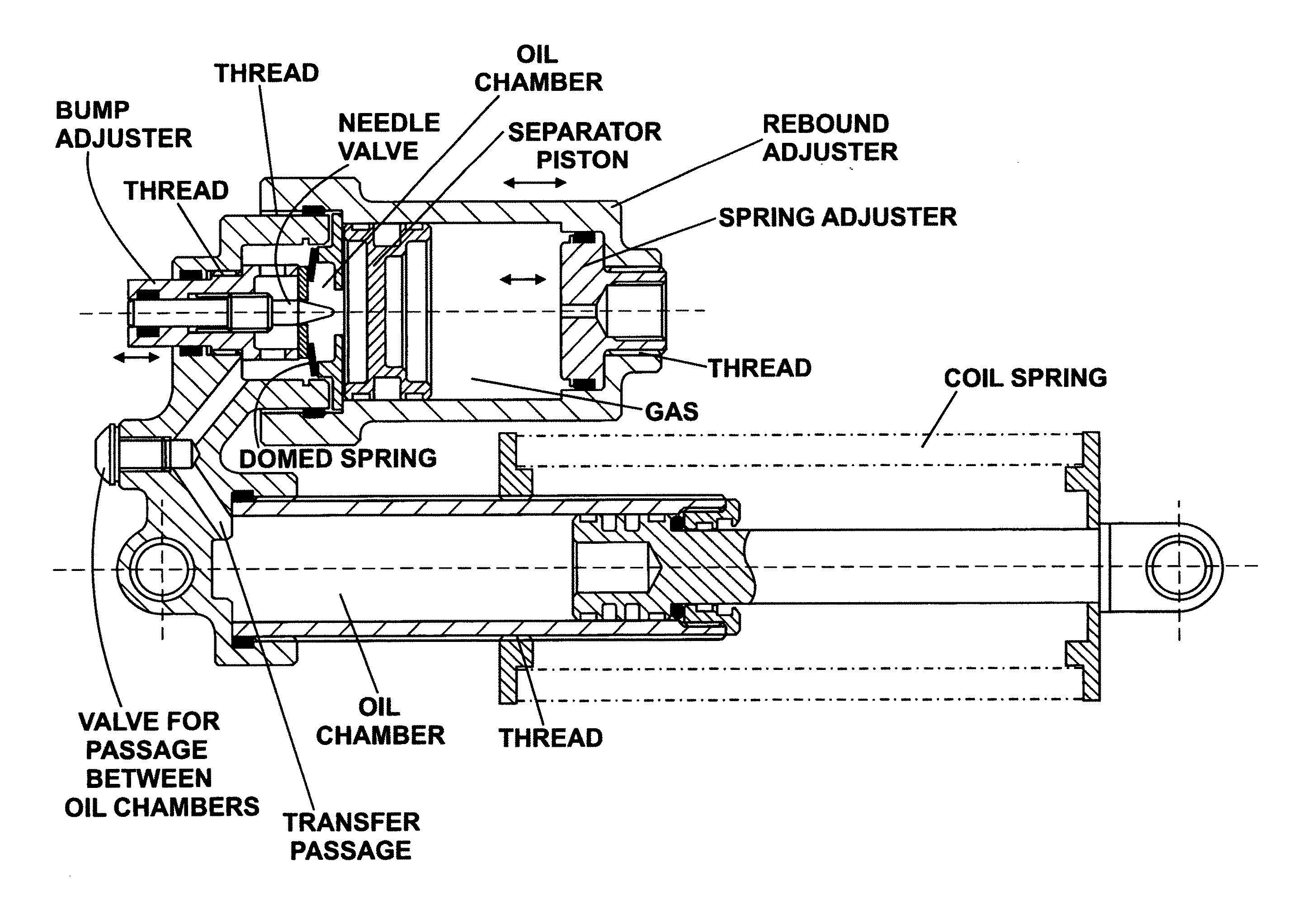
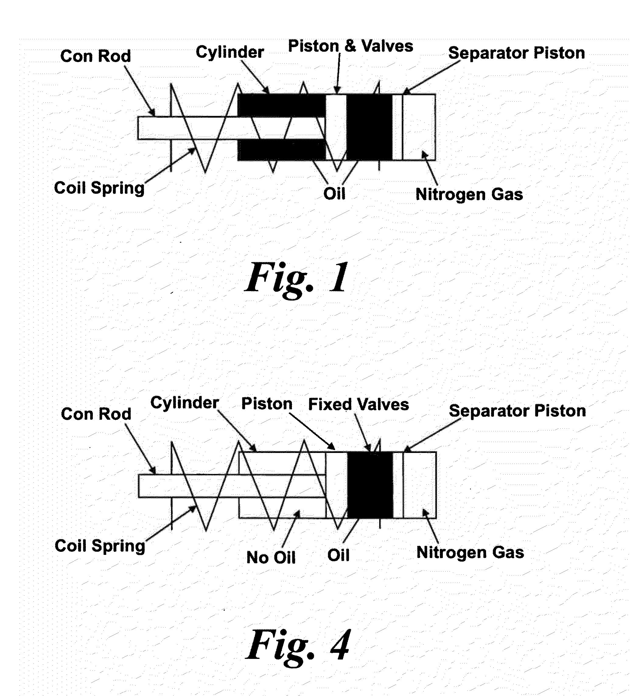
[0090]With reference to FIG. 4 there is shown an over-coil shock absorber assembly in which the damping valves are detached from the piston and are provided in an oil chamber so as to divide the oil chamber into two sub-chambers. This changes the gas spring generation from con-rod displacement to a solid piston (oil is retained on one side only). The assembly also comprises gas chamber which is separate from the oil chamber but which applies pressure to the oil in the oil chamber.

[0091]This arrangement enables Nitrogen gas in the gas chamber to act on the full area to the right side of the piston only. The left side can be open to atmosphere or under vacuum, thus providing the maximum differential pressure between the two sides.

[0092]This increases the proportion of supporting forces generated by the Nitrogen gas, along with a corresponding reduction in coil spring force, as compared with a similarly rated known shock absorber assembly.

[0093]This layout does not have to incorporate ...


PUM


Abstract

A shock absorber assembly comprises a piston and cylinder arrangement, a damping-fluid chamber and a damping valve arrangement which is located in the damping fluid chamber and serves to divide the chamber into sub-chambers. The assembly is such that in use the valve arrangement regulates the flow of fluid between the sub-chambers.

Description

FIELD OF INVENTION[0001]The present invention relates generally to suspension systems and in particular to shock absorber assemblies for vehicles.BACKGROUND[0002]For a vehicle without suspension to move over a rough surface, the whole vehicle must rise and fall over every bump. The faster the vehicle moves, the more rapid becomes this up-and-down motion. Bumps hit at high speed can push the vehicle up very hard, but cannot fall back any faster than gravity pulls it. Therefore, even at moderate speeds, the wheel can leave the ground over the top of bumps. A wheel in the air cannot give any grip.[0003]Technology can provide a considerable amount of power, but it is useless unless the tyres are kept in firm contact with the road. Modern vehicle suspensions, acting with the pneumatic tyres, isolate the vehicle, driver and load from these vertical forces. They control the vertical oscillations, caused by traversing uneven terrain or performing rapid manoeuvres such as accelerating, braki...

Claims


Application Information

Patent Timeline
Patent Type & Authority Applications(United States)
IPC IPC(8): F16F9/44F16F9/096
CPCB60G11/15B60G11/30B60G13/08B60G2202/12B60G2202/24B60G2500/30F16F9/064F16F9/462F16F9/466F16F9/56
Inventor HUNTER, JOSEPH RICHARD ANDREW
Owner HUNTER
Why Eureka
Try Eureka