Paper sheet storing and feeding unit

Active Publication Date: 2010-07-01
GLORY KOGYO KK
View PDF6 Cites 32 Cited by
  • Summary
  • Abstract
  • Description
  • Claims
  • Application Information

AI Technical Summary

Benefits of technology

[0034]According to a paper sheet storing and feeding unit of the present invention, the maximum

Problems solved by technology

Therefore, it is impossible to stably store and feed banknotes.
That is, it is difficult for the conventional banknote storing and feeding unit to increase the maximum storage quantity of banknotes.
However, since the pressing roller is fixed, the outer diameter of the winding drum is regulated, and it is difficult to increase the maximum storage quantity of banknotes.
Further, since the tapes are largely folded by the pressing roller, a banknote is folded reversely to the winding direction of the winding drum and there is a possibility of causing trouble with the storage state of banknotes wound and stored around the winding drum, in the case of using tapes each having a width short

Method used


Image

  • Paper sheet storing and feeding unit
  • Paper sheet storing and feeding unit
  • Paper sheet storing and feeding unit

Examples


Example

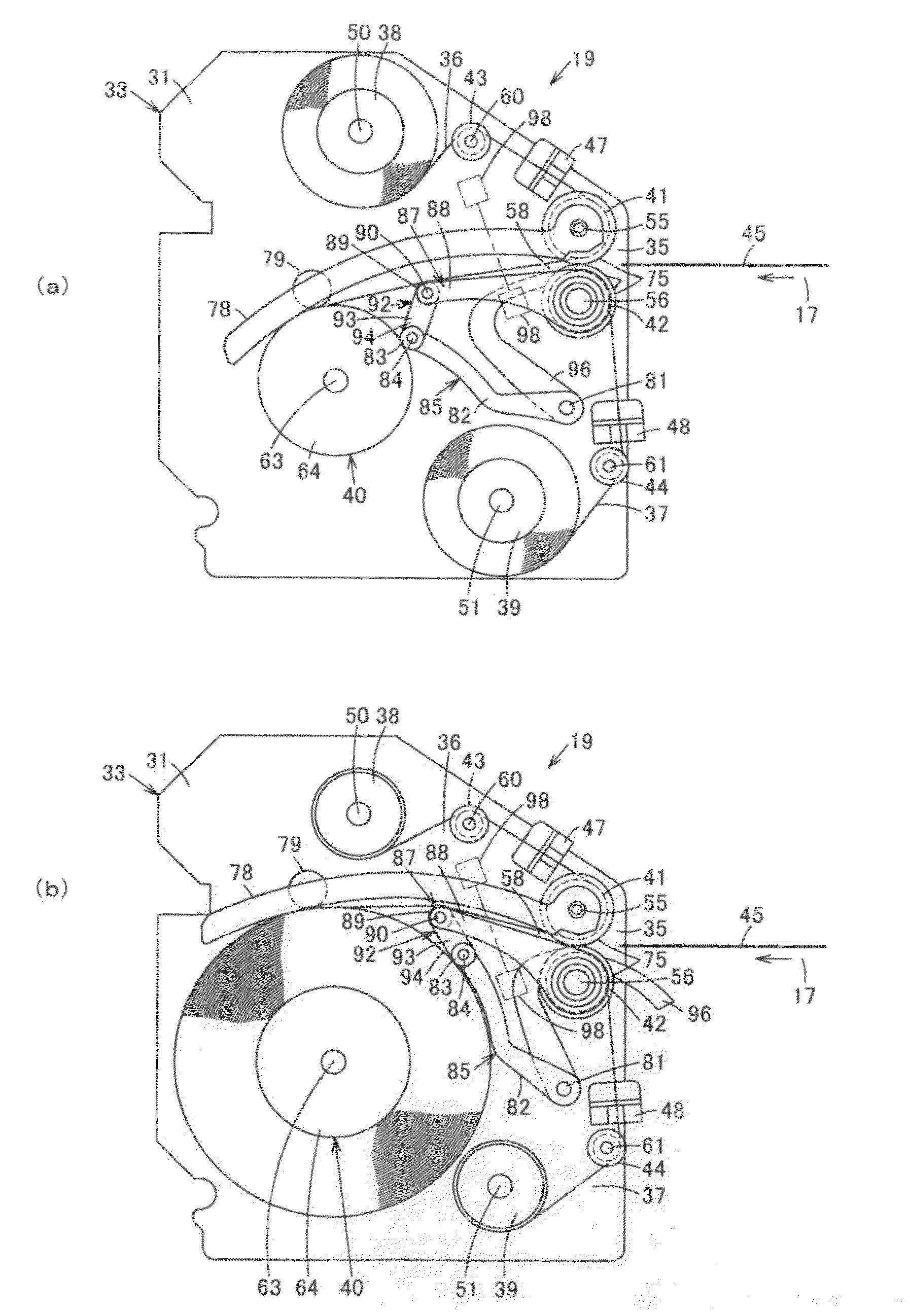
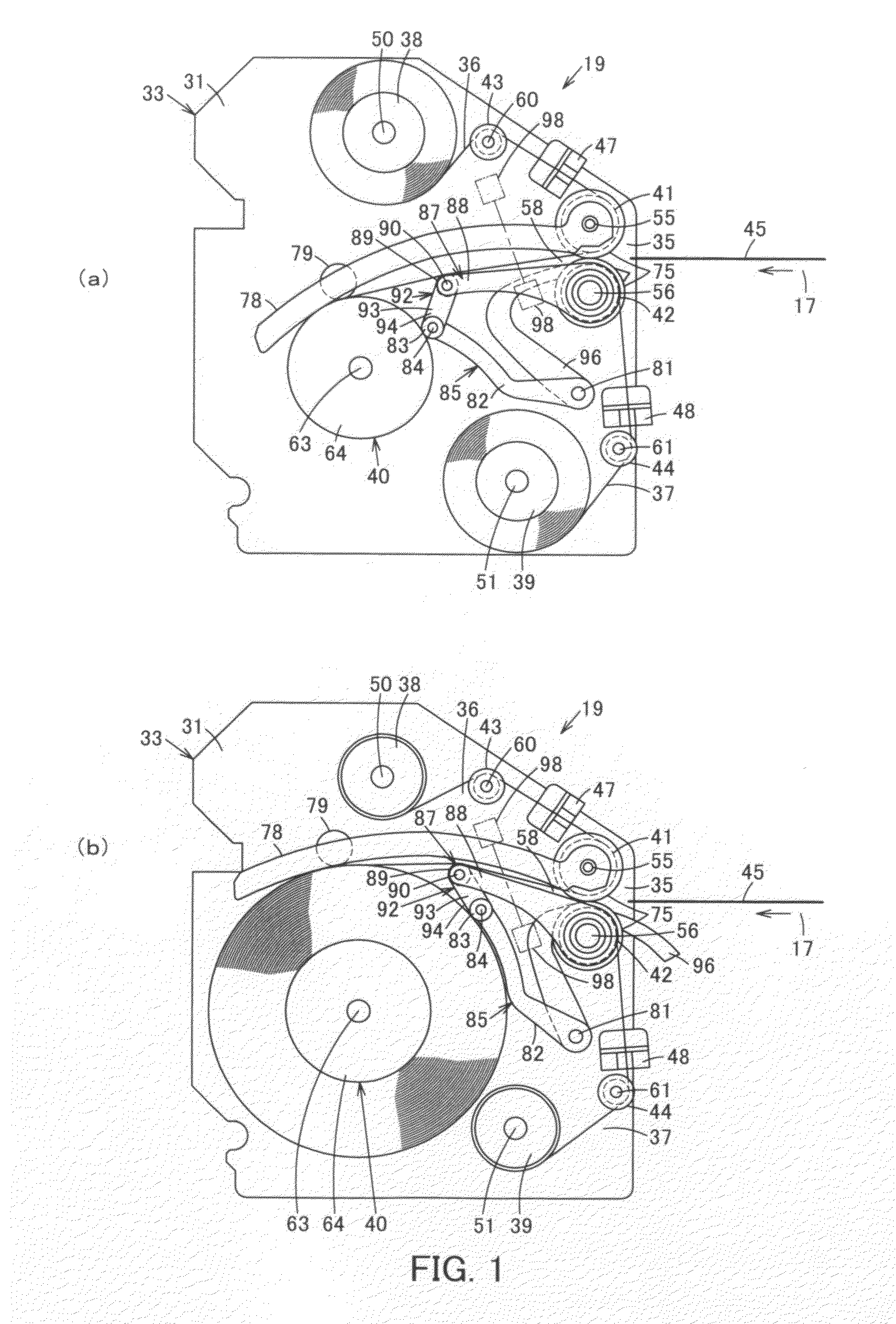
[0045]FIGS. 1 to 5 show a first embodiment.

[0046]FIG. 5 shows a banknote processing machine as a paper sheet processing machine. A banknote processing machine 11 is a banknote depositing and dispensing machine for depositing and dispensing banknotes as paper sheets, and an upper block 13 and a lower block 14 capable of being drawn out from a machine body 12 are provided in the machine body 12.

[0047]In the upper block 13, there are disposed: an inlet 15 for depositing banknotes; an outlet 16 for dispensing banknotes; a transport path 17 for transporting banknotes; a recognition unit 18 for recognizing banknotes transported on the transport path 17; and a banknote storing and feeding unit 19 as a paper sheet storing and feeding unit which is an escrow unit for escrowing banknotes one by one in the separated state.

[0048]In the lower block 14, stackers 20 for storing banknotes for each denomination which are juxtaposed back and forth; and a cassette 21 for storing banknotes is arranged ...

Example

[0100]Next, FIGS. 6 and 7 show a second embodiment.

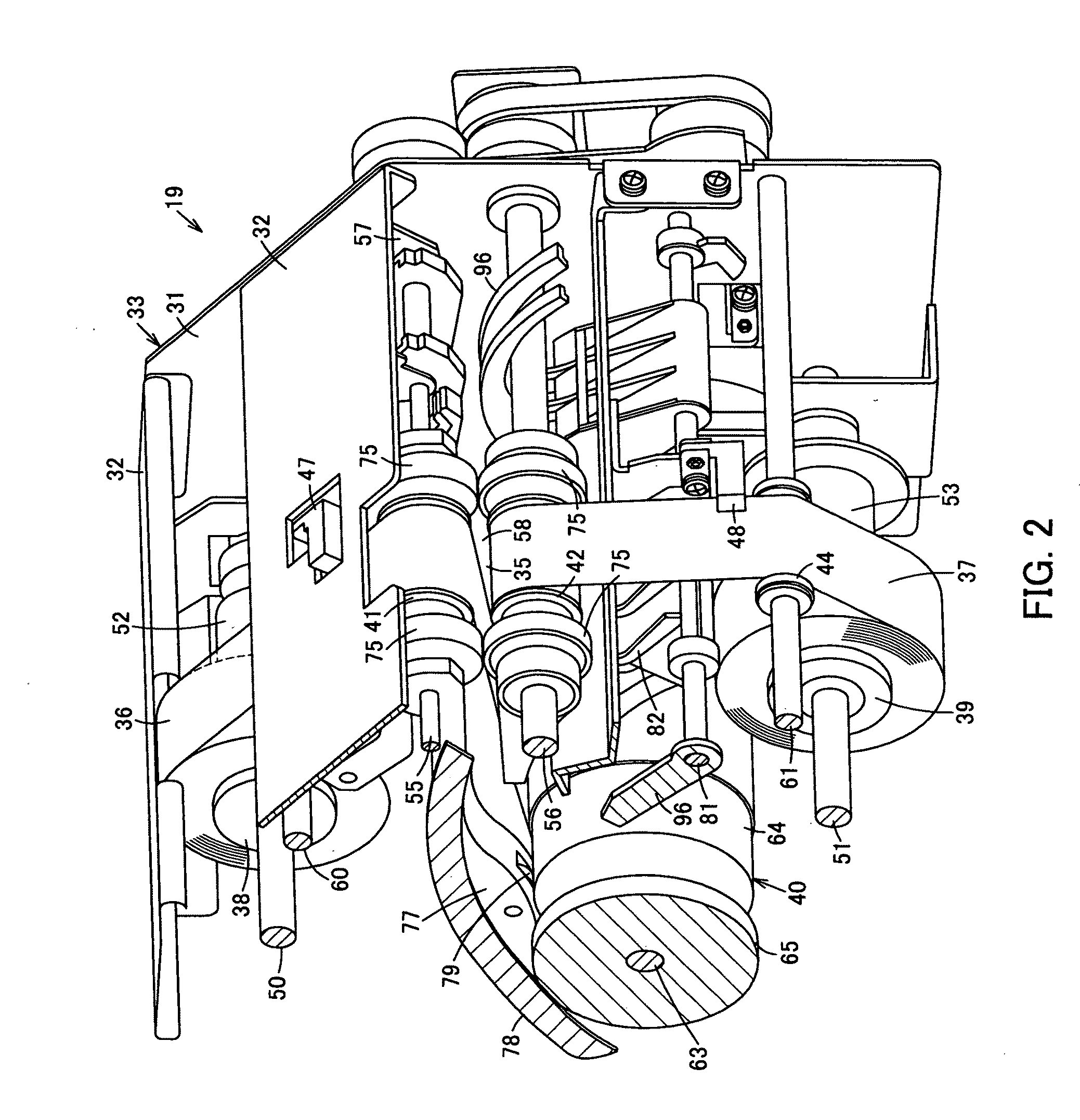
[0101]As shown in FIG. 6, the outer diameter detecting unit 85 includes: the support axis 81, the swinging lever 82, the contact roller 83, the contact roller axis 84 and a contact body movement amount detecting unit 101 for detecting the movement amount of the contact roller 83 following and moving in accordance with the outer diameter of the portion of the winding drum 40 around which both tapes 36 and 37 are wound. For example, a potentiometer, rotary encoder or the like for detecting the movement amount of the contact roller 83 based on the rotation amount of the swinging lever 82 around the support axis 81 is used for the contact body movement amount detecting unit 101. Moreover, although the swinging lever 82 here rotationally moves, a supporting system for making the contact roller 83 linearly move may be adopted. In this case, a sensor for detecting the linear movement amount is used.

[0102]As the moving unit 92, the interloc...

Example

[0107]Next, FIG. 8 shows a third embodiment.

[0108]As the outer diameter detecting unit 85 of the second embodiment described above, in place of the contact body movement amount detecting unit 101, a non-contact detection sensor 108 is used which detects, without contact, the outer diameter of the portion of the winding drum 40 around which both tapes 36 and 37 are wound. The non-contact detection sensor 108, for example, irradiates an LED light to the portion of the winding drum 40 around which both tapes 36 and 37 are wound, measures light reflected from there by use of a photodiode to measure a distance between the non-contact detection sensor 108 and the portion of the winding drum 40 around which both tapes 36 and 37 are wound.

[0109]Also in this case, the control unit 104 shown in FIG. 7 is used.

[0110]The control unit 104 can determine the outer diameter of the winding drum 40 based on the distance between the non-contact detection sensor 108 and the winding drum 40 detected by ...


PUM

PropertyMeasurementUnit
Diameteraaaaaaaaaa

Abstract

The present invention is to provide a banknote storing and feeding unit 19 capable of increasing the maximum storage quantity of banknote 45 and stably storing and feeding banknote 45.
A first tape 36 and a second tape 37 are pressed by a tape pressing body 87 between first and second winding reels 38 and 39 and a winding drum 40 so as to come into contact with each other. Even the banknote 45 having a short length in a transporting direction is held between the first tape 36 and second tape 37 at a position of the tape pressing body 87 for transportation. An outer diameter of the winding drum 40 is detected by an outer diameter detecting unit 85, and the tape pressing body 87 is moved by a moving unit 92 in accordance with the detected outer diameter of the winding drum 40, and the tape pressing body 87 is moved to an appropriate position following a change in the outer diameter of the winding drum 40. Thus, the maximum storage quantity of the banknote 45 can be increased and the banknote 45 can be stably stored and fed.

Description

CROSS-REFERENCE TO RELATED APPLICATION[0001]This application is a continuation-in-part of International Application No. PCT / JP2007 / 070263 filed Oct. 17, 2007 (now pending).TECHNICAL FIELD[0002]The present invention relates to a paper sheet storing and feeding unit which stores and feeds paper sheets by winding and unwinding tapes.BACKGROUND ART[0003]In a banknote processing machine such as a banknote depositing and dispensing machine for depositing and dispensing banknotes as paper sheets, for example, a tape storage type banknote storing and feeding unit using two tapes for storing and feeding banknotes has been conventionally used.[0004]In the banknote storing and feeding unit, two tapes are used, one end side of the respective tapes is attached to two winding reels and wound around the reels, the other end side of the respective tapes, facing each other, is attached to one winding drum and wound around the drum. The respective tapes between the two winding reels and the winding d...

Claims


Application Information

Patent Timeline
IPC IPC(8): B65H5/28
CPCB65H29/006B65H2301/4191B65H2301/41912B65H2511/14B65H2553/00B65H2701/1912B65H2220/01
Inventor MIZORO, TSUGUO
Owner GLORY KOGYO KK
Why Eureka
Try Eureka